Get in touch with Ebestron Company


Updated November 2026
Luer Lock Dispensing Needles connect a dispensing tip to a syringe or adapter with a tapered fitting and locking collar. For industrial dispensing, choosing the needle means evaluating the connection, the fluid-contact materials, and the outlet position together.
A replacement could screw onto the syringe and put its outlet in a different position. A wet needle can also have a sound connector: liquid may be emerging from the bore, creeping along the outside, or escaping from a separate upstream joint. The location of the first wet area may indicate what to check next.
Quick connection facts
- Locking features retain the connection; mating tapered surfaces form the fluid seal.
- Needle gauge, bore diameter, tube length and installed reach describe different features.
- A lined steel needle still has a hub and an attachment joint to consider.
- Locate the first wet area before changing a dispensing setting.
Luer Lock Dispensing Needles use a tapered connection and locking features to attach a needle hub to a compatible outlet. Check the mating parts, installed reach and complete fluid path before approving a replacement.
What a Luer lock dispensing needle does
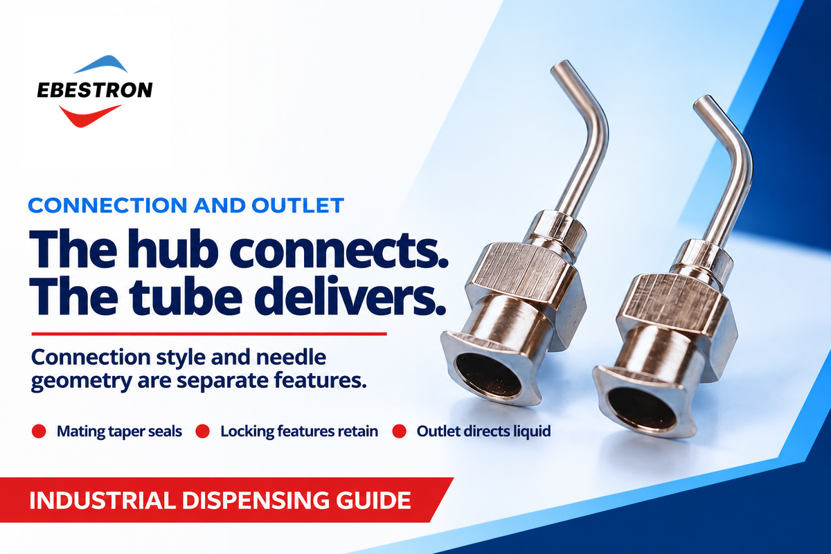
The connector creates the fluid path, and the needle directs liquid to the workpiece. While similar, the features may vary independently. A blunt tip dispensing needle describes an outlet style and application. It doesn’t describe every feature of the locking mechanism.
What is a Luer lock needle?
A Luer lock needle is a needle assembly whose hub mates with a tapered outlet and engages its locking features. In industrial dispensing, the tube places adhesive or liquid at the application point. “Luer lock” refers to the connection style; bluntness, bore size, tube material, and use are other considerations.
According to Bruce Hansel’s explanation of Luer connections, the mating cones have a 6% taper. Contact between the surfaces forms the seal. A threaded skirt engages the receiving component’s lugs to resist separation. Therefore, tight-looking threads can still sit over damage or contamination between the sealing surfaces, and a joint can look connected while being too loose to stop a leak.
The International Organization for Standardization’s ISO 80369-7:2021 addresses intravascular or hypodermic connectors. Sharing that connector name doesn’t make an industrial needle suitable for medical use, and it doesn’t give the dispensing assembly a working-pressure rating. This guide concerns adhesive placement and industrial liquid handling.
Match the syringe, hub and adapter
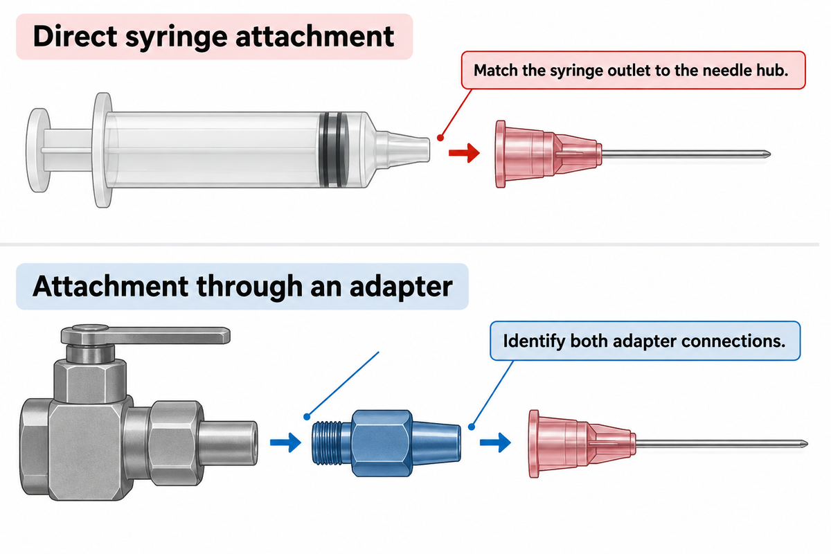
Work from the equipment outlet and follow the component chain. Some systems accept a needle directly on a Luer lock syringe. Others use an adapter to connect a dispensing valve to the needle hub. In the latter case, the adapter has two connections to identify.
Can you put a needle on a Luer lock syringe?
A compatible Luer lock needle hub can connect to the corresponding outlet on a Luer lock syringe. Verify the syringe and needle instructions for service and industry, and verify that the needle hub and the outlet mate properly. The connector must seat correctly, and the assembled needle must clear the fixture before the syringe is used in a dispensing process.
Read an adapter’s upstream thread and downstream needle connection separately. Specify the valve connection’s sealing arrangement, installed height and thread separately. Photograph the stack of components with its part numbers for reference.
For a needle with Luer lock attachment, identify the mating outlet before choosing the bore. When comparing tips with Luer lock hubs, keep the adapter reference beside each candidate.
An example from history demonstrates the importance of requiring the complete pair. In the U.S. Food and Drug Administration’s 2013 draft on glass-syringe connectivity, incompatibilities were documented between components meeting different component standards because of omitted mating dimensions. So check the mating dimensions of both parts, not just the connection label.
Direct syringe attachment
- Match the syringe outlet to the needle hub.
- Check clearance around the syringe nose.
- Locate outlet position from the assembled syringe.
Attachment through an adapter
- Identify both adapter connections.
- Check clearance around the valve and adapter.
- Locate outlet position from the complete stack.
The distinction matters when ordering a spare dispenser needle: retaining the needle part number while substituting the adapter can still change the installation. Keep the upstream connection details while specifying the blunt tips with Luer lock hubs.
Separate connector fit from installed needle position
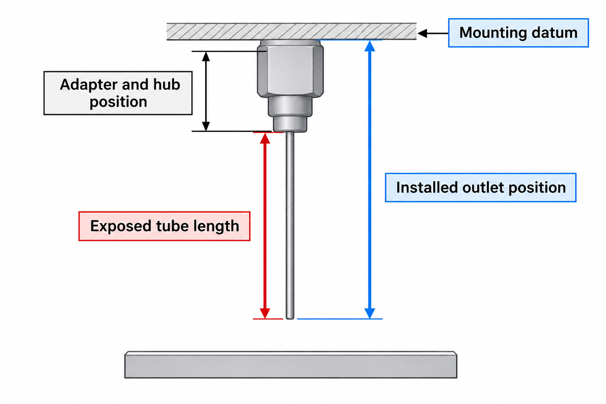
Connector fit focuses on the mating surfaces. The installed position of a needle tip concerns its relationship to the machine and the workpiece.
Installed Reach Stack
Installed Reach Stack separates the fixture datum, adapter, hub and exposed tube so a replacement’s outlet position can be checked.
| Feature | What it tells you | What to record |
|---|---|---|
| Bore diameter | Opening through which the liquid travels | Drawing-defined internal diameter and product family |
| Tube outside diameter | Clearance through a hole or beside a wall | Outside diameter at the working section |
| Exposed tube length | Tube projection from its defined starting point | Manufacturer’s length datum |
| Adapter and hub position | Where the tube begins in the assembled stack | Mounting datum to hub/tube transition |
| Mounting datum | Reference from which the installation is measured | Fixture or valve mounting reference |
| Hub envelope | Space occupied around the connection | Clearance to nearby tooling |
| Bend orientation | Direction of the outlet on an angled needle | Orientation relative to the mounting datum |
| Workpiece standoff | Gap from the installed outlet to the target | Approved motion-program position and target surface |
| Installed outlet position | Where liquid exits relative to the workpiece | Assembled reach, bend orientation and fixture clearance |
Product-family details matter even when the gauge stays the same. Nordson’s Optimum General Purpose table lists its 25G steel tip with a 0.25 mm bore and 0.52 mm outside diameter. Its PTFE-lined 25G table lists a 0.30 mm bore. These are published values for those specific product families, rather than a universal 25G conversion.
The same General Purpose catalog separates 12.7 mm (0.5 inch), 25.4 mm (1 inch) and 38.1 mm (1.5 inch) tube-length columns. When ordering 1 inch dispensing needle tips from this family, check the assembled outlet position separately. Tube length is only one dimension in the complete adapter-to-workpiece stack. For bore selection, use the separate dispensing needle gauge selection guide.
Hypothetical installation: A process engineer is replacing a straight needle and its adapter as part of a fixture change. The hub seats, but the outlet now reaches farther into a recess. Before retracing the existing motion path, the engineer verifies the assembled reach and clearance from the fixture datum. Matching only tube length would miss the changed adapter position.
Lessons in measurement appear in an EEVblog post on the measurement of blunt needles. One contributor revised his assessment of an internal diameter measurement after another contributor questioned the caliper method. Document how the small bore was measured; rely on a dimensional drawing or an appropriate inspection method if that bore controls the decision. Treat the small internal opening of a precision tip as an inspection feature rather than estimating its size from the outside.
Check every component in the fluid path
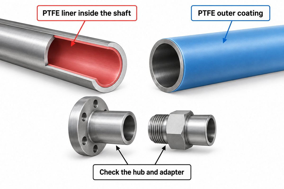
A stainless steel tube is only one element of a stainless steel dispensing needle assembly. The liquid may contact the hub, adapter and attachment region. A change of material has to be assessed over that path, including the actual adhesive chemistry and exposure conditions.
“Factors like rheology, chemistry and mix ratio must be carefully considered when selecting a material for dispensing.”
PTFE lining and PTFE outer coating address different surfaces. Nordson describes its lined construction as a PTFE liner inside a crimped stainless steel shaft. Their selection guidance addresses exterior coating for reducing liquid wicking. Neither description makes the complete hub-and-adapter assembly a solid PTFE component.
A polypropylene hub, a metal tube and a liner belong on separate material fields in a specification. The same applies to a plastic tapered tip: its connector and flow geometry still need checking even though the tube construction differs. With tapered tip dispensing, keep the construction details with the process specification. For a low viscosity fluid, distinguish an exterior-wetting concern from the internal flow path before choosing a surface treatment.
Hypothetical fluid change: The production team changes the adhesive while keeping the needle. Procurement checks the whole wetted assembly against the new fluid and cleaning instructions before treating the unchanged steel tube as evidence of suitability.
Usage history is also included here. Lane and Miller’s historical thermoplastic Luer study examined the effect of loading history on test pieces. Assess repeated assembly and first-use fit separately.
Assemble the connected dispensing system
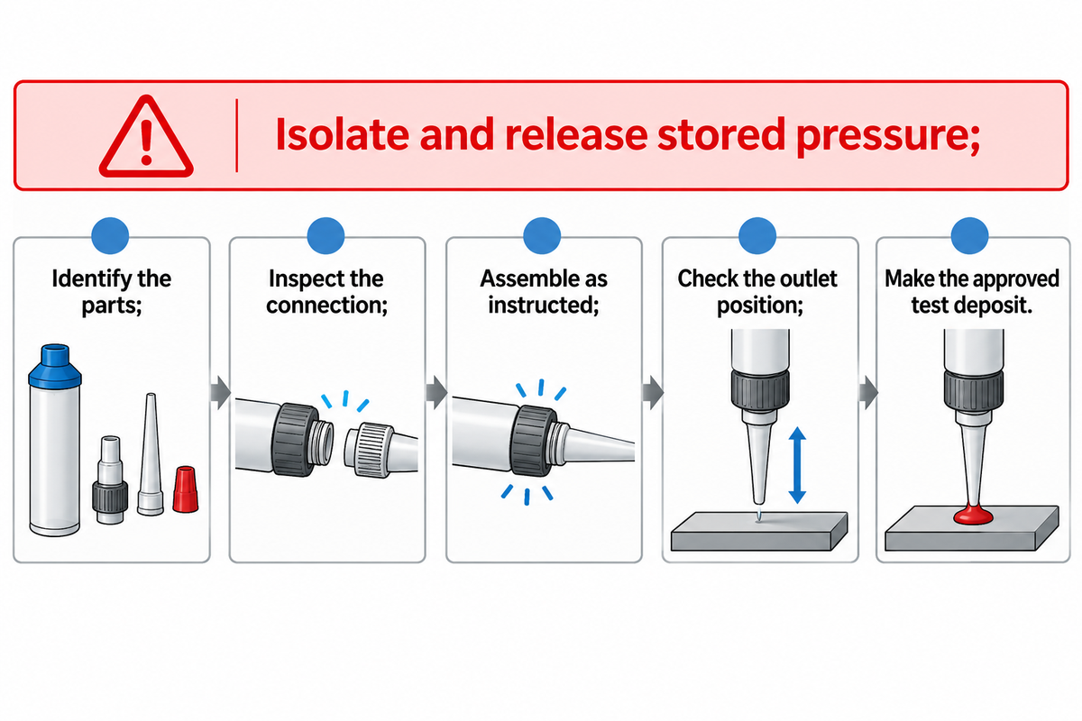
Use the matched equipment instructions to assemble the syringe, adapter and needle and verify the outlet position. Keep connection checks separate from changes to dispensing pressure, timing or the motion program.
Safe setup: Before handling or disconnecting components, isolate the dispenser and release stored pressure using the dispenser’s operating procedure. Assembly and operating limits of individual components should be followed. An improvised tool shouldn’t be used to torque a connection that won’t seat.
- Identify the parts — compare the syringe, adapter and needle references with the approved assembly.
- Inspect the connection — check accessible mating surfaces and locking features for residue or damage under the equipment procedure.
- Assemble as instructed — use the prescribed engagement method for those components.
- Check the outlet position — verify reach, orientation and fixture clearance before motion.
- Make the approved test deposit — observe the assembled system under the established process conditions.
A secure appearing syringe needle has passed only a visual assembly check. Process release also depends on the required deposit and the machine setup. If a refill is allowed by equipment procedure, repeat the prescribed equipment setup checks before restarting the applicator. To continue with general setup and tuning the deposit for the blunt-tip dispensing system, refer to the blunt-tip dispensing guide.
Find where the connected assembly is leaking
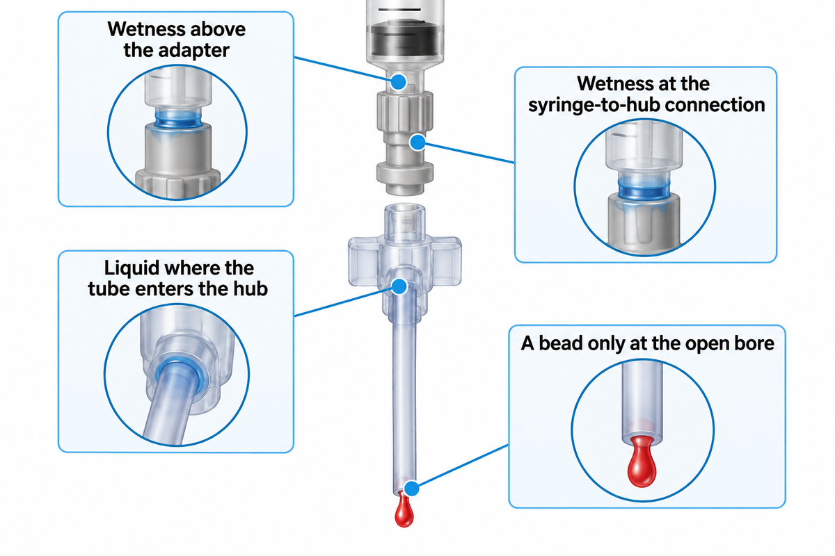
When looking for leaks, distinguish liquid escaping through an unwanted joint from liquid leaving through the intended outlet. Clean, dry external surfaces make the location easier to identify, when cleaning is permitted by the equipment and fluid procedures. Observe from a safe position; isolate and depressurize for inspection or replacement.
3-Interface Leak Trace
3-Interface Leak Trace separates an upstream adapter joint, hub connection and tube attachment, and differentiates these joints from an open outlet.
Many causes can bring about the same observation. Start from where the wetness first appears and use the table below to pick the next check.
| First observation | Candidate explanation | Next component or condition to check |
|---|---|---|
| Wetness begins above the adapter | The upstream joint is the starting point | Valve-to-adapter connection and its specified seal |
| Wetness begins around the syringe-to-hub connection | Mating surfaces, part pairing or condition needs checking | Syringe nose, hub and engagement |
| Liquid appears where tube enters hub | The tube attachment region needs inspection | Needle assembly; distinguish this joint from the locking collar |
| A bead forms only at the open bore after a shot | Residual drive, trapped air or cutoff behavior may be involved | Barrel, piston and dispenser settings under the approved process |
| Liquid travels upward along the tube exterior | Exterior wetting may resemble a higher leak | First appearance of liquid and external surface condition |
| A new matched needle resolves wetness at the old hub | The removed component or its condition becomes a stronger lead | Retain old/new part and condition records; inspect the isolated old assembly |
| Wetness returns after repeated needle changes | The mating component or assembly history remains a candidate | Adapter or syringe outlet, residue, damage and reuse instructions |
| Outlet behavior changes after a new prefilled barrel | Barrel contents or piston setup may have changed | Barrel and piston configuration before changing the connector |
| Air appears during a process with suck-back, while the exterior stays dry | Air ingress requires a different investigation from visible liquid leakage | Actual pressure direction, approved air-leak checks and other air-entry paths |
One reason to check upstream is trapped air. Nordson’s syringe-barrel guidance states that, after liquid dispensing, compressed air can expand and push liquid out. It also states that a prefilled barrel isn’t always paired with the best piston for the application. A dripping outlet therefore gives a different starting point from a wet locking collar. If the complaint is a clog or no flow, follow the approved procedure for blockage rather than treating it as a connection leak.
Pressure direction also matters. The Estonian Centre for Standardisation’s description of ISO 80369-20:2024 distinguishes pressure-decay leakage from subatmospheric air leakage and aspiration. Those medical test categories show why suck-back needs its own air-leak check: a joint that stays dry outside can still let air in.
A National Institute of Standards and Technology-hosted review of microfluidic leakage testing likewise emphasizes application-specific characterization. Document the actual fluid and the operating conditions and direction of the pressure difference when referring the concern to the equipment supplier.
Hypothetical troubleshooting: An operator sees a bead at the bore after dispensing adhesive, but the hub and adapter remain dry. The next check is the barrel/piston and cutoff setup. The starting point, however, becomes the joint upstream from the adapter if liquid appears above the adapter. Replacing the needle in both situations would be treating two different apparent faults as one.
Specify the complete assembly for your next order
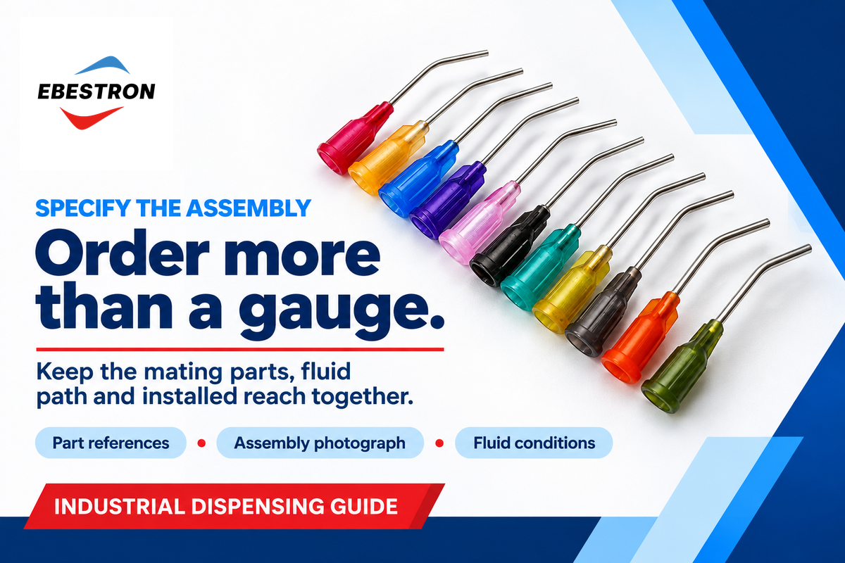
Order industrial dispensing needles as a defined assembly, rather than a gauge plus pack size. Procurement needs the component references for its selection of Luer lock components; the process engineer needs the installed geometry; quality staff need an inspection basis that distinguishes new parts from used ones.
Provide the mating syringe or valve, any adapter and both of its connections, the needle hub, bore and outside diameter, drawing defined tube length, bend orientation and assembled reach. Indicate the fluid, cleaning exposure and intended replacement practice. Record whether the parts are new or used, whether the process includes suck-back, and whether the connection remains assembled or is repeatedly disconnected. If the purchase is for a disposable needle, preserve that use condition instead of assuming repeated cleaning is acceptable.
Use drawings alongside the assembly photograph to document dimensions. For precise dispensing, the specified dimensions reflect the target deposit and access to the workpiece. A supplier can then distinguish an acceptable substitute from a component that merely attaches.
Send Ebestron the existing part references, an assembly photograph and the fluid conditions when discussing Luer lock dispensing needles. Use the current assembly as a baseline. Check any change to the adapter, the wetted materials and the installed outlet before allowing it on the existing machine program.
Discuss the complete connection
Share the syringe or valve outlet, adapter details and required needle reach with Ebestron.
Frequently Asked Questions
What needles work with luer lock?
Needles with a Luer lock hub, a 6% tapered socket with lugs, fit syringes and adapters that have the matching threaded Luer lock outlet, subject to the component instructions and intended fluid service. Check the actual syringe or adapter reference as well as the needle. Gauge and hub color help identify a product, but neither replaces the mating-part and dimensional information needed for an industrial assembly.
What is the difference between a luer lock syringe and a regular syringe?
A Luer lock syringe has locking features around its tapered outlet that engage a compatible receiving hub. “Regular syringe” is an imprecise description: it may mean a slip-tip syringe or another outlet design. A slip-tip connection relies on contact and friction between mating tapers, without the additional locking skirt. Identify the actual outlet before choosing a replacement.
How to attach needle to luer lock syringe?
Seat the matched needle hub on the syringe’s tapered outlet and engage its locking features using the syringe and needle manufacturers’ assembly instructions, with the dispensing equipment isolated as required by its procedure. Identify the correct parts, inspect their accessible mating features and use the specified engagement method. Check the final outlet position before making the approved test deposit; stop to investigate a connection that doesn’t seat normally.
Does a Luer lock connection determine the dose?
No. The connector retains a fluid connection, while the complete dispensing process determines the deposit. Barrel and piston behavior, metering settings, liquid properties and the downstream flow path all belong in a dose investigation. Measure the resulting deposit against the process target.
Are all needles luer lock?
No. Needles can use different hubs, fixed attachments or other connection designs. A blunt industrial needle describes its tip geometry, rather than one universal hub. Identify the required connection before comparing bore or length. When a listing uses only “syringe needle,” obtain its component drawing or mating-part details rather than inferring a Luer lock connection from the name.
Are industrial blunt needles suitable for injection?
An industrial blunt tip isn’t a substitute for a needle qualified for medical use. Industrial adhesive handling and injection have different intended-use requirements. Select a medically qualified device through the appropriate clinical process rather than using an industrial dispensing product.
Is an outer PTFE coating the same as a liner?
No. An outer coating changes the surface that liquid encounters outside the needle; a liner forms part of the internal flow path. A coating selected for exterior wetting behavior is therefore different from a liner selected for contact with the dispensed fluid.
The connection maps organize inspection points for industrial dispensing. The examples are fictitious; they don’t illustrate Ebestron customer cases. About Ebestron.
References & Sources
- Anesthesia Patient Safety Foundation, Managing Luer Connections
- International Organization for Standardization, ISO 80369-7:2021
- ASSEMBLY, Troubleshooting the Dispensing Process, Jim Camillo
- MD+DI, Lane and Miller’s thermoplastic Luer study
- Estonian Centre for Standardisation, ISO 80369-20:2024 description
- National Institute of Standards and Technology, Overcoming Technological Barriers in Microfluidics: Leakage Testing
- U.S. Food and Drug Administration, glass-syringe connectivity, 2013 draft