
Get in touch with Ebestron Company


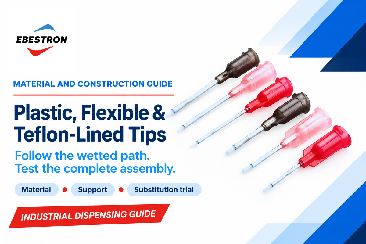
The options in the adhesive dispensing tips category are described by the type of material they’re made of, their flexibility or internal construction. Start with the surface that touches the fluid: a flexible polymer tube, a supported PTFE liner, and an exterior PTFE coating. Then, consider the complete assembly and compare their behavior under the same dispensing conditions.
PTFE and polypropylene tubing can be found in flexible tips. Stainless steel tips can be rigid and contain a PTFE liner. Those combinations explain why changing a catalog label sometimes changes both the chemistry at the wall and the mechanical behavior at the work surface.
Updated November 2026
Quick construction facts
- Plastic identifies a polymer family; specify polypropylene, polyethylene or another resin.
- Flexible describes mechanical behavior; it doesn’t identify the wetted polymer.
- PTFE-lined identifies an internal flow path; coated identifies a surface treatment whose location matters.
- Compare actual bore, exposed length and hub construction before substituting a tip.
Plastic, Flexible & Teflon-Lined Tips differ in wetted material and mechanical support. Use a compatible polymer flow path for the adhesive, flexibility for access, and a controlled trial to compare the complete tip assembly.
Key points
- Flexible PTFE tubing and PTFE-lined metal are separate constructions.
- Exterior wetting and an internal blockage need different checks.
- Keep startup, steady dispensing and restart results separate.
- Tip price becomes useful when compared with accepted deposits and changeover losses.
Plastic, Flexible and Lined Describe Different Things
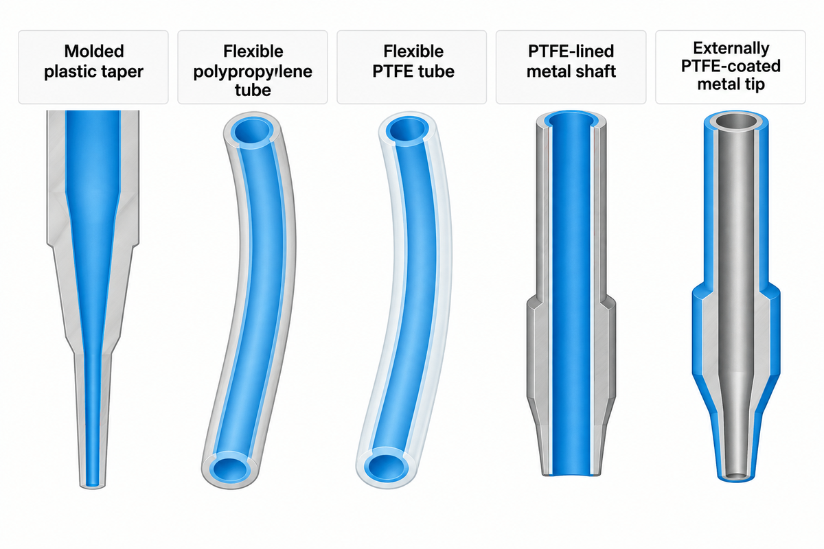
Plastic, flexible and lined describe a material category, a mechanical property and an internal layer within a supporting body, respectively. A product can fit in more than one category. In order to truly understand adhesive dispensing tips, consider the tube, the support, the tip hubs, and the surface that comes in contact with the fluid.
The broader industrial dispensing needles and precision tips range includes several geometries. Different flow paths are created by a molded taper. The mold shape and the resin used to manufacture the part are separate specification fields.
| Construction | Fluid-contact surface | Mechanical behavior | Useful distinction |
|---|---|---|---|
| Molded plastic taper | Specified molded polymer | Usually holds its molded shape | Taper geometry and polymer grade both matter |
| Flexible polypropylene tube | Polypropylene tube, plus exposed hub/joint surfaces | Tube bends during access or contact | Flexibility does not make it PTFE |
| Flexible PTFE tube | PTFE tube, plus exposed hub/joint surfaces | Unsupported polymer tube can bend | A PTFE tube is not necessarily a metal-supported liner |
| PTFE-lined metal shaft | PTFE in the lined region; other exposed surfaces at transitions | The metal shaft supports the PTFE liner | Inspect the liner termination and outlet construction |
| Externally PTFE-coated metal tip | Metal bore unless the part also has an internal treatment | Rigid shaft with treated exterior | Exterior coating addresses a different contact surface |
What is the difference between a dispensing tip and a dispensing needle?
“Dispensing Tip” is the broader term; a dispensing needle often describes a tubular cannula that delivers the fluid. Catalogs refer to flexible and lined assemblies as needle tips. Tip selection starts with the construction description and part number when ordering; therefore, a naming preference doesn’t take the place of the required fluid-contact material or geometry.
A blunt metal tip used for grease and a plastic taper used for viscous sealant can share the same syringe connection while behaving differently at the outlet. A luer lock provides a twist-on connection; secure attachment still requires the mating components to engage correctly. Connection compatibility and performance of the dispensing tip are two separate checks.
PTFE-Lined vs PTFE-Coated: Follow the Fluid
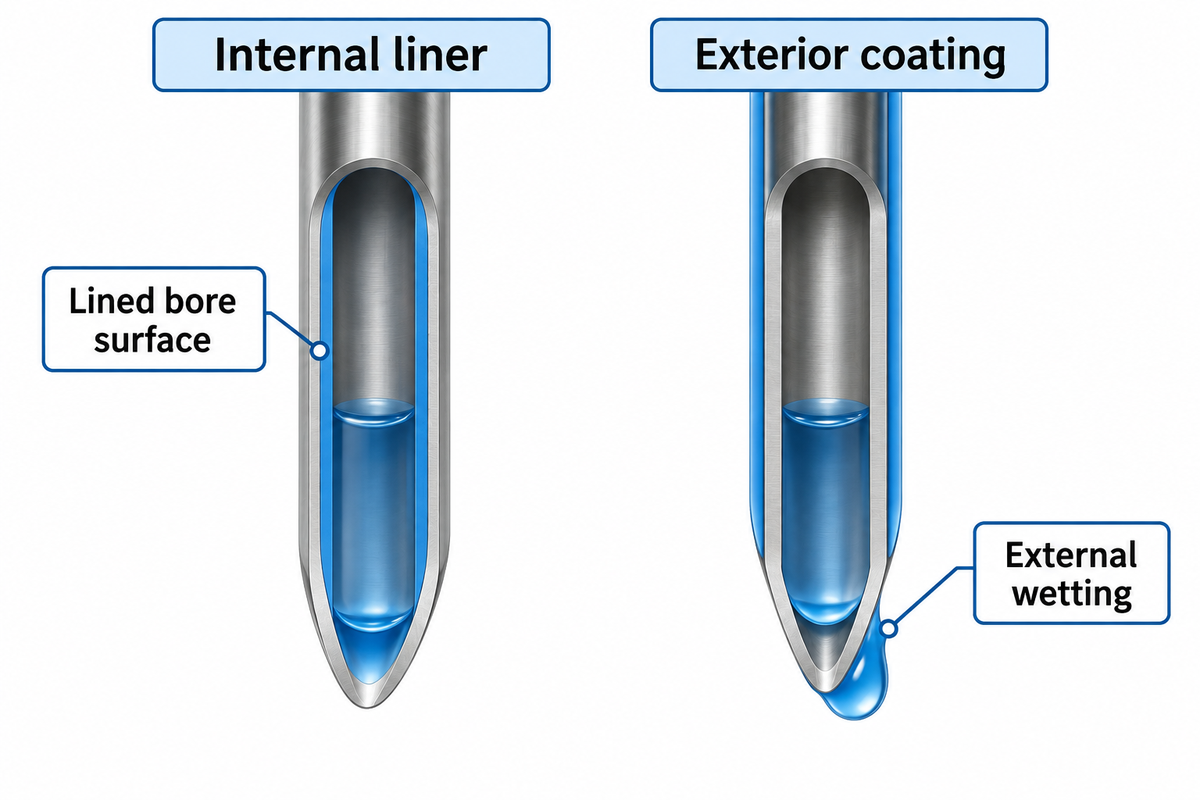
An internal PTFE liner changes the surface along the lined bore; an exterior PTFE coating changes the surface around the outside. Nordson EFD’s lined series is targeted for low-viscosity fluids such as cyanoacrylates. Its coated series is described for wicking control and clean cutoff. Select the surface treatment to address the issue.
Wicking describes fluid creeping along the outer surface of a tip, and a build-up of drops on the outside can disrupt placement of a fluid deposit, even if the bore is open. An obstruction in a tip restricts the path through which fluid must pass. A coating chosen for exterior wetting won’t remove a cured obstruction from metal surfaces inside the bore. A non-stick exterior and a PTFE liner therefore belong in different rows of a troubleshooting record.
Internal liner
- An internal PTFE liner changes the wetted bore surface and receives mechanical support from the surrounding shaft. An exterior PTFE coating changes external wetting while retaining the shaft’s support. The liner termination, outlet construction and coating location distinguish the two assemblies.
- The surrounding shaft supports the liner.
- The liner end and outlet need a defined construction.
Exterior coating
- An exterior coating changes wetting around the outer surface.
- The coated shaft retains its mechanical support.
- The coating needs a defined surface location.
Nordson’s product tables illustrate another substitution trap: its 25G lined tip lists a 0.30 mm inner diameter, while the 25G coated tip lists a 0.25 mm inner diameter.
PTFE-lined dispensing tips are candidates for specified reactive formulations; the lining does not remove the formulation’s cure mechanism. For teflon-lined dispensing tips, specify the lined assembly along with low viscosity materials and cyanoacrylates.
Flexible Polypropylene vs Flexible PTFE: Shape Is Not Chemistry
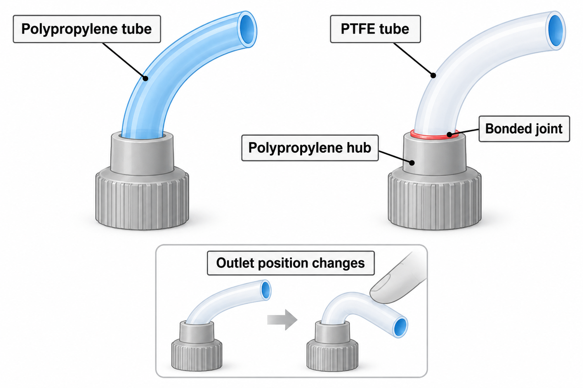
Jensen Global’s flexible-tip range has PTFE tubing and a separate polypropylene flexible family. Jensen describes its PTFE tube as bonded with a UV-cured adhesive to a polypropylene hub. Flexibility supplies access; the tube polymer and bonded connection determine which materials are present along the assembly. As such, neither description can replace the other.
PTFE and Polypropylene are different polymers. Flexible tips prevent direct metal-shaft contact at the outlet when the entire contacting tube end is polymer. A curved reach requirement doesn’t choose between the two. The adhesive formulation, exposed joints and operating conditions still need to match the chosen assembly. Jensen describes cutting its polypropylene tubing to a customized length; keep any permitted trimming procedure tied to the particular product.
When should I use a flexible tip instead of a steel needle?
Use a flexible tip when a rigid shaft obstructs access to a recess or when incidental contact with a delicate workpiece is the main concern. A flexible tube can take a different approach path. However, bending a tube alters the position of the outlet. Keep a rigid construction when the process requires the shaft to hold its location under the expected contact load.
Example: an assembly station applies small quantities of adhesive around a finished enclosure’s curved interior. A rigid tip reaches the first section, but touches the wall for the rest of the path. The operator suggests a flexible polypropylene tube. That is a reasonable access change to compare, but replacing the part alone would leave two questions unanswered: where does the tube end move under contact, and does the chosen adhesive suit the tube and hub joint? Run the intended path on representative workpieces while recording outlet position and surface marking. A tube that bends away from the surface yet misses the bond line has solved the contact problem without meeting the deposit requirement.
Check the Complete Wetted Path Before Matching Adhesives
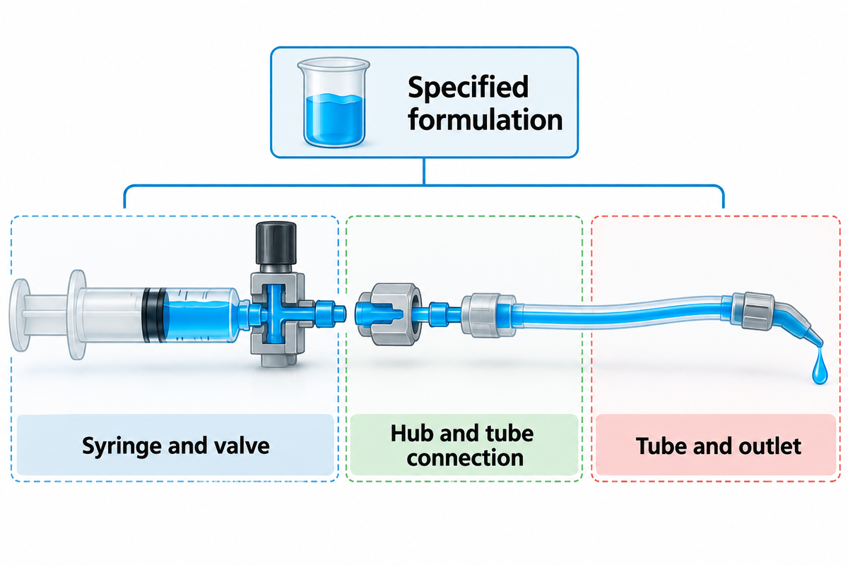
The wetted path includes every component the adhesive touches before reaching the substrate. The path includes the syringe and any dispensing valves. It includes the hub, tube connection and outlet. A suitable PTFE tube can be connected to a different polymer hub or an adhesive bond, so qualify the assembled fluid path with the intended formulation.
Shailesh Lad’s material-first discussion in ASSEMBLY’s Know Your Fluids relates fluid properties and choice of dispensing system.
List the fluid’s product name and formulation grade rather than only epoxy or anaerobic adhesive. For a light-curable fluid, include the exposure conditions along the entire path. A black hub and a UV blocking tube are of different specifications. Filler introduces solid particles that a plain viscosity value doesn’t describe. An epoxy with filler and a silicone sealant belong to different formulation records, and neither should inherit a trial result of solder paste.
For the metering geometry, use the dispensing needle gauge selection guide for bore, tip length and flow selection. Here, those dimensions are controlled comparison inputs: changing them with the polymer makes a material-only explanation harder to support.
NIST’s rheology overview distinguishes constant-viscosity Newtonian fluids from fluids whose viscosity changes with shear rate. A single viscosity value is therefore an incomplete description for some pastes. A 2026 polymer-gel study by Yamasaki and colleagues also measured adhesion to PTFE, and found that measured adhesion didn’t strictly follow the simple surface-energy ranking. It’s better to consider low surface energy a material property as opposed to considering that material always exhibits zero adhesion.
Example: a station dispensing thin cyanoacrylate runs normally during continuous work but has trouble after the operator’s regular pause. A proposed PTFE-tube assembly changes the tube and its connection to the hub. Record the adhesive’s age and the actual pause, then inspect whether the disturbance first appears inside the outlet, around the joint or on the exterior. For the comparison, keep the upstream syringe barrels and the metering assembly the same. An improvement during continuous dispensing would leave the restart complaint unresolved. Quality control needs deposits from that restart condition before procurement approves the substitute for the same production task.
Use a 3-Condition Material Substitution Trial
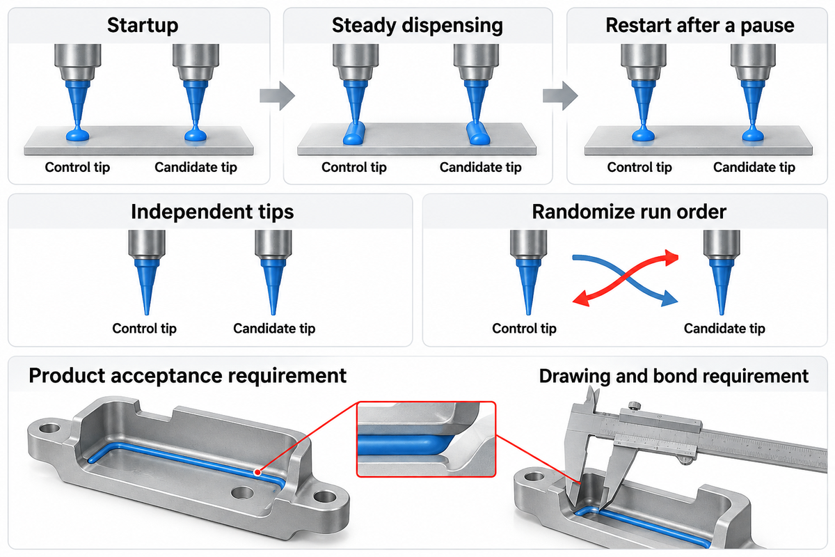
The material substitution trial compares startup, steady dispensing and restart after a production pause.
Use this proposed screening method to evaluate which operating condition changes when an assembly is substituted. Begin with the existing acceptable part and compare the candidate at the required delivered quantity. Independent tips and separate runs matter: repeated shots from a single tip describe that run, rather than independent replications of a material treatment.
NIST’s experimental-design glossary distinguishes experimental units, replication and blocking. Allocate independent tip assemblies to the candidates, randomize run order within practical blocks, and record adhesive batch, operator and run time. Record all solvent exposure in the handling record. If actual bore or exposed length can’t be matched, consider this as an assembly comparison. A causal material study needs those confounders controlled.
| Field or condition | Control assembly | Candidate assembly | Record for comparison |
|---|---|---|---|
| Part identity | Current approved part and lot | Candidate part and lot | Separate identifiers for each independent tip |
| Fluid | Specified cyanoacrylate formulation and batch | Same formulation and batch within a block | Age and handling history |
| Internal construction | Current tube/liner and hub joint | Candidate tube/liner and hub joint | Which fluid-contact surfaces changed |
| Geometry | Published actual bore and exposed length | Matched geometry where feasible | Unmatched fields remain confounders |
| Motion | Current approach and withdrawal path | Same path during the initial screen | Contact, bending and outlet position |
| Startup | First deposits under the normal startup procedure | First deposits under the same procedure | Mass or dimensions and any required discard |
| Steady dispensing | Normal production bead or dot sequence | Same required deposit and cadence | Deposit variation and visible residue |
| Pause and restart | Actual production pause and handling | Same pause and handling | First deposits after restart, logged separately |
| Independent repeats | Fresh units in separate runs | Fresh units in separate runs | Run order, operator, batch and time block |
| Acceptance decision | Existing product requirements | Same product requirements | Pass/fail by condition, then retained settings |
“Including replication allows an estimate of the random error independent of any lack of fit error.”
Set pass/fail limits from the workpiece drawing and bond requirement, and then examine the candidate’s results. Use the same measuring method for both assemblies. If the candidate requires different valve timing or pressure to give the target deposit, preserve this as a separate functional-qualification result and don’t quietly integrate it with the initial controlled comparison.
A purchasing objection generally occurs here: the replacement costs less and has the specified gauge, so why provide more samples? A different bore, bonded joint or restart result changes what production is buying. Release the defined assembly and its retained setup.
Read Material-Related Failure Patterns
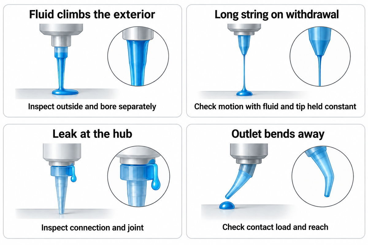
Separate a blocked bore, external wetting and a fluid string before choosing a different polymer. An outlet that appears to be clear during steady dispensing can still clog mid-run or after a pause. A long fluid bridge can occur with a fluid that has the property of deforming and with the motion of withdrawal.
Chan and colleagues’ 2023 liquid-bridge study examined a commercial thermal paste with thixotropic elastoviscoplastic behavior. Its dispensing ligaments illustrate why a string alone isn’t a material diagnosis. Keep motion and fluid behavior in the investigation alongside the tip’s wetted surface.
| Observation | Competing explanation | First comparison | Replacement or release action |
|---|---|---|---|
| Clog or no flow after a pause | Residue or cured material at the outlet; upstream interruption | Locate the restriction using the approved maintenance procedure | Replace a blocked or damaged consumable |
| Fluid climbs the exterior | External wetting; fluid left on the shaft | Inspect the outside separately from the bore | Compare a defined exterior treatment |
| Long string on withdrawal | Fluid elasticity; withdrawal path; wetting | Hold the fluid and tip constant while checking motion | Retain settings that meet the deposit requirement |
| Leak at the hub | Connection engagement; damaged hub or joint | Inspect the connection after isolating the system | Replace a damaged assembly |
| Tube softens or changes shape | Chemical exposure; temperature; mechanical loading | Compare an unused matching tip and exposure history | Remove the altered assembly from service |
| Outlet bends away from the target | Contact load; unsupported reach | Observe the tip along the intended motion path | Revise reach/support or choose a stiffer construction |
| Workpiece marking | Contact force; edge condition; trapped residue | Inspect contact location and outlet condition | Remove the cause before releasing the path |
| Irregularity after trimming | Uneven cut; changed length | Compare the cut end with an unmodified permitted part | Retain only the qualified cut procedure |
| Intermittent interruption with filled fluid | Particle population; agglomerate; flow-path restriction | Check formulation and actual bore together | Change one controlled input before comparison |
| Light-curable residue in the path | Unintended light exposure; handling delay | Trace exposed tubing, hub and outlet | Use the formulation’s specified light-protection setup |
For a damaged liner, softened tube or a leaking bonded connection, increasing back-pressure leaves the failed component in place. Isolate and service the system under its approved procedure before another run. The diagnostic table prioritizes the next comparison. The observation resulting from that comparison must still be evaluated against the product’s acceptance requirement.
Example: A paste application starts to string after a change of tip family. The replacement tip has a different unsupported length, and its outlet moves during withdrawal. Production calls the new polymer sticky, while purchasing points to the matching tip gauge. First, repeat the current part using the same paste batch and motion. Then compare the candidate part with its outlet position along the complete path. If the withdrawal path also changed, maintain separate results for that change. This sequence distinguishes an assembly or motion effect from a material claim without assuming that an exterior coating will fix every string or drool event.
Compare Material Changes by Cost per Accepted Deposit
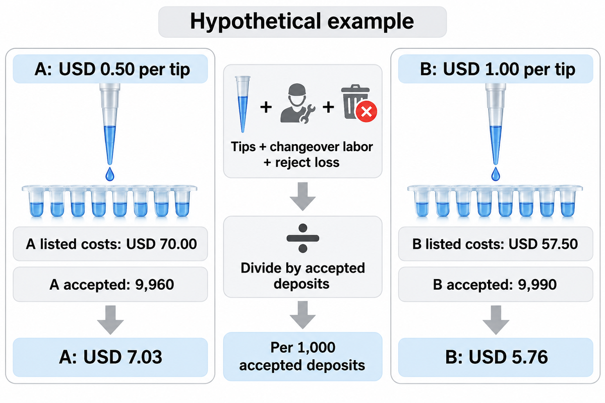
Flexible and PTFE-lined tips have part-specific prices rather than a fixed premium over molded plastic tips. Compare quotes for the required construction, actual dimensions and order quantity. For a production decision, combine the quoted unit price with measured consumption and accepted output; paying less per tip does not necessarily reduce the cost of the deposits that pass inspection.
Compare the listed tip-related costs per accepted deposit, rather than tip price alone. Include consumed tips, changeover labor and attributable reject loss in the numerator, and state accepted output in the denominator. For a full production cost comparison, include manufacturing costs allocated for the different accepted outputs.
Assumed inputs: each option attempts 10,000 deposits. Option A consumes 100 tips at USD 0.50 each, takes 20 min of changeover labor, and has 40 attributable rejects. Option B consumes 50 tips at USD 1.00 each, takes 10 min of changeover labor, and has 10 attributable rejects. Labor is USD 0.50/min and incremental reject loss is USD 0.25/deposit.
| Cost or output | Option A | Option B |
|---|---|---|
| Tip consumption | 100 × USD 0.50 = USD 50.00 | 50 × USD 1.00 = USD 50.00 |
| Changeover labor | 20 min × USD 0.50/min = USD 10.00 | 10 min × USD 0.50/min = USD 5.00 |
| Incremental reject loss | 40 × USD 0.25 = USD 10.00 | 10 × USD 0.25 = USD 2.50 |
| Listed costs | USD 70.00 | USD 57.50 |
| Accepted deposits | 10,000 − 40 = 9,960 | 10,000 − 10 = 9,990 |
| Listed cost per 1,000 accepted | 70.00 ÷ 9,960 × 1,000 = USD 7.03 | 57.50 ÷ 9,990 × 1,000 = USD 5.76 |
With the assumptions provided, the more expensive tip has the lower listed cost per accepted output. Record observed consumption and rejects before replacing the assumptions. Don’t charge the same changeover labor as downtime, or add a reject cost that’s accounted for elsewhere.
A finance reviewer can then evaluate the additional trial expense relative to the production volume. A small-quantity intermittent operation and a high volume production line may reach different purchasing decisions even if they use the same part.
Specify the Material Construction You Actually Qualified
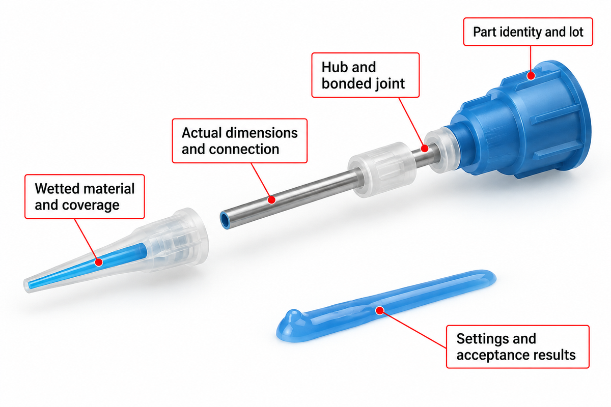
Specify the successful assembly by wetted material, support, actual dimensions and connection. Retain operating settings and acceptance results with part identity. Order by actual bore, exposed length and connection rather than hub color or nominal gauge size, since tips with the same gauge label can have different bores.
For procurement, collect the following information in a single request: polymer grade; liner and coating coverage; actual inner and outer diameter; exposed length; liner termination; hub and bonded-joint materials; connection drawing; allowed trimming or reuse; part numbers and lot identification; and the intended fluid and pause conditions. Requirements of light protection and part cleanliness should also be included if applicable.
Do
- Retain the tested assembly identity.
- Carry acceptance results into the order.
- Record substitute-specific settings.
Don’t
- Color-only ordering.
- Substitution of exterior coating for internal lining.
- Unqualified changes to the hub joint.
Ebestron supplies the plastic tapered, flexible polypropylene and PTFE-lined families described on its plastic, flexible and PTFE-lined tip configurations page. Use that product route for the available assembly and sample inquiry once the material and access requirements for those specific applications are defined.
Frequently Asked Questions
Are the hub colors a fixed standard across suppliers?
No. Treat color as an identifier within the named manufacturer’s product family. Two tips carrying the same gauge label can have different bores or colors when their construction changes. Order against the actual part number, published inner diameter, exposed length and connection, then compare those fields when considering another supplier.
Can I reuse a dispense tip?
Reuse a dispense tip only when the tip manufacturer’s procedure permits it for the fluid and service involved; replace a blocked or damaged consumable with a fresh tip. Cured residue, a distorted outlet or liner damage changes the flow path. Any permitted reuse needs the same deposit checks used for production.
Can I order custom dispense tips?
Yes, custom construction can be requested from suppliers that offer that service. Describe the wetted material, actual bore, outer dimensions, exposed length, hub and access requirement instead of requesting a gauge alone. A proposed drawing and sample define the assembly to qualify before a custom quotation becomes an approved production replacement.
Does PTFE stop every adhesive from curing?
No. PTFE changes a contact surface; it doesn’t remove an adhesive’s polymerization mechanism, mixed-material working life or exposure to curing light. A fast-curing formulation can still leave residue and obstruct an outlet during its service cycle.
Can a black tip be assumed to protect a light-curable adhesive?
No. Specify the required light protection for the formulation, including the tube and hub rather than color alone. A light-curable adhesive can contact a bonded joint or an exposed outlet before reaching the workpiece. Keep lighting and handling conditions consistent during the comparison, and include the production pause. If either the formulation or the exposed component changes, retain that change with the assembly’s acceptance results instead of carrying forward the previous light-protection assumption.
Does trimming a flexible tip change the process?
Yes. Trimming changes exposed length and creates a new outlet edge. For products with a permitted cutting procedure, inspect the cut and repeat the deposit check. Record the resulting length with the assembly so the next replacement has a repeatable outlet position.
What should change when a tip supplier or product family changes?
When a tip supplier or product family changes, compare the replacement’s wetted materials, actual dimensions, hub connection, liner termination and bonded joints with the successful part. Keep startup, normal dispensing and restart observations separate. Fresh independent tips and balanced run order help distinguish part differences from time or handling effects. If the substitute needs different settings, retain those with its identity and results. Matching nominal gauge labels alone leaves several construction fields unresolved.
Match the tip construction to the job
Send Ebestron the adhesive formulation, required deposit, access drawing and production pause, together with the current assembly description. Request a candidate configuration to compare against the retained part and acceptance criteria.
Learn about Ebestron’s dispensing-consumables business.
References & Sources
- Know Your Fluids Shailesh Lad, ASSEMBLY, 2007.
- Rheology National Institute of Standards and Technology.
- Polymer Gels Exhibiting High Pressure-Sensitive Adhesion to Polytetrafluoroethylene Yamasaki et al., Polymers, 2026.
- A Glossary of DOE Terminology NIST/SEMATECH e-Handbook of Statistical Methods.
- Edge fracture of thixotropic elastoviscoplastic liquid bridges Chan et al., PNAS Nexus, 2023.