Get in touch with Ebestron Company


Selection essentials
- Read the actual bore in the named tip family.
- Shortlist for deposit and access, fluid behavior, and available dispensing time.
- Keep the tip part number with the successful trial conditions.
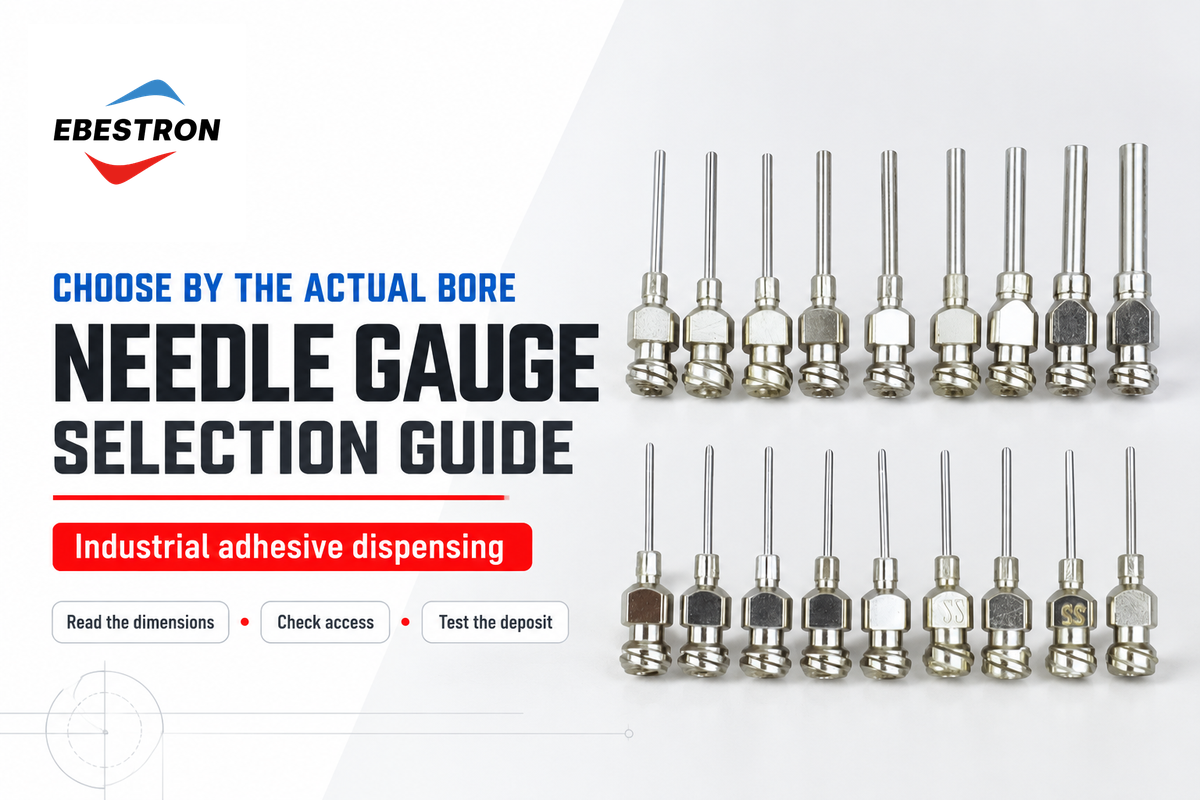
Choosing the right needle gauge begins with the actual inner diameter, adhesive behavior, and access to the joint. Then compare sample tips on the dispenser that makes the part. This Dispensing Needle Gauge Selection Guide shows how to narrow the choice, without treating a gauge number as a universal bore or a finished glue-dot size.
A dispensing needle gauge selection guide correlates catalogue dimensions with a required deposit. First, consider the bore and tip geometries, and then check the fluid, access and timing constraints prior to determining the production quantity.
Updated October 2026
This reference offers information on interchangeable industrial syringe and contact-dispensing tips. Internal needles and nozzles in jet valves need the equipment maker’s selection method. For other product families, please refer to our industrial dispensing needle range.
Read a Dispensing Needle Gauge Chart by Bore
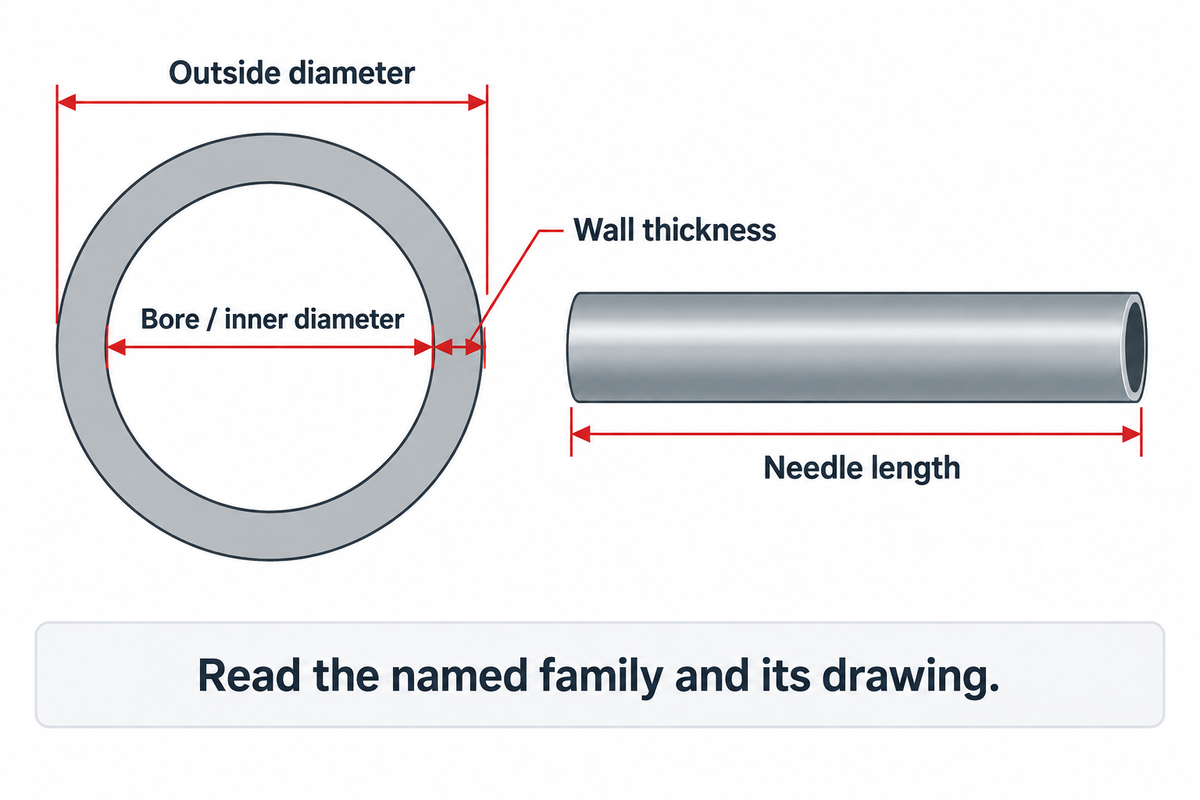
Jensen lists a 20 gauge needle with a 0.600 mm bore in its NT series and a 0.635 mm bore in its IT series. The gauge label matches, but the openings and hub colors differ. Read needle gauges, together with the manufacturer’s series, inner diameter, length and part number.
Within a numbered series, larger gauge needles generally have finer openings, with gauge numbers indicating the size sequence. Phrases such as “larger gauge” or “smaller gauge needle” can confuse an order because people may mean either the number or the physical size. Specify the bore in millimeters when you want to say what size needle to order.
| Manufacturer and family | Gauge | Published inner diameter | Hub color |
|---|---|---|---|
| Jensen NT | 20G | 0.600 mm | Pink |
| Jensen IT | 20G | 0.635 mm | Yellow |
| Jensen NT | 22G | 0.410 mm | Blue |
| Jensen IT | 22G | 0.508 mm | Black |
| Jensen NT | 23G | 0.340 mm | Orange |
| Jensen IT | 23G | 0.406 mm | Sky blue |
| Jensen NT | 25G | 0.260 mm | Red |
| Jensen IT | 25G | 0.305 mm | Blue |
| Fisnar single tapered | 20G | 0.60 mm | Pink |
| Fisnar double tapered | 20G | 0.58 mm | Pink |
These are the millimeter values from Jensen’s standard-tip and Fisnar’s tapered-tip tables. Each row corresponds to that manufacturer’s named family. Use the associated dimensional drawing to select a replacement; equal gauge labels can mean different flow paths and connectors.
What does a dispensing tip gauge chart actually tell you?
Dispensing tip gauge charts list nominal sizes within a product family. ID refers to the opening of the fluid; OD is the measurement of the profile of the outside of the tip. Wall thickness connects those two dimensions. Length and hub construction complete the tip and identify it for comparison.
When choosing the right gauge, read the row rather than the color swatch. The table shows a blue hub identifying two different needle sizes across Jensen’s series. Using the wrong series chart can therefore alter the bore ordered. In the drawing, distinguish the thickness of the needle wall from the diameter of its bore. For Ebestron product specifications and purchasing options, see our stainless steel precision tips.
Choose a Bore for Your Adhesive and Deposit
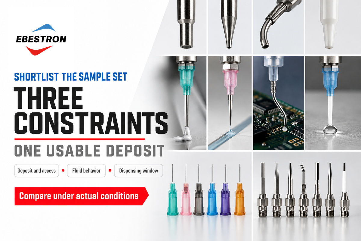
Start with the time available, the size of the deposit that must fit on the part, and the adhesive that must flow through the tip. These reduce the number of appropriate needle gauge candidates. The final selection is based upon pressure capability, the behavior of the fillers and the actual transfer to the substrate.
Understanding the factors that determine a usable deposit helps separate a tip problem from a process constraint. Smaller needles can reach tight locations, but access is only one of the factors to consider. Selecting the appropriate needle also needs enough output during permitted delivery time. The proper needle must satisfy both access and output requirements.
Viscosity is one input. NIST’s rheology guidance explains that non-Newtonian viscosity changes with shear rate. Temperature, shear conditions and fillers affect how a viscosity value informs tip selection. Use the adhesive supplier’s measurement conditions and filler information when comparing candidate tips. Particle loading and agglomeration can influence the choice of needle even when two materials carry similar viscosity figures.
Three-Constraint Tip Selector
Tips are shortlisted by deposit and access, fluid behavior, and dispensing window using the Three-Constraint Tip Selector.
| Constraint | Observed requirement | Candidate to compare | What decides the choice |
|---|---|---|---|
| Deposit/access | Small exposed dot | Fine straight tip | Deposit footprint and clean transfer |
| Deposit/access | Recessed bond joint | Longer slim cannula | Reach without collision or bending |
| Deposit/access | Delicate adjacent surface | Compatible flexible tip | Clearance and positional control |
| Fluid | Thick unfilled paste | Tapered tip or larger bore | Output within equipment pressure limits |
| Fluid | Particle-filled adhesive | Larger clear flow path | Filler size, loading and clogging behavior |
| Fluid | Fast-curing cyanoacrylate | Suitable PTFE-lined construction | Material compatibility and usable working time |
| Fluid | Light-curable adhesive | Compatible light-blocking path | Protection from relevant curing wavelengths |
| Time | Required shot misses the window | Shorter or less restrictive geometry | Target volume and completed transfer |
| Time | Dot forms but tails during withdrawal | Current tip with controlled transfer settings | Stand-off, dwell and retraction behavior |
Consider a hypothetical example of an electronics assembly with a small exposed bond pad. A straight fine tip is a good starting point because the access is straight-forward and the footprint is small. If the deposit spreads beyond the pad, a smaller bore alone may not fix it; check the shot volume, substrate wettability and tip position first.
Let’s consider a filled epoxy bead on an accessible flange. Put a tapered tip and a less restrictive bore in the sample set, and preserve the formulation’s particle information. Forcing a fine tip to create the bead by raising pressure may create a more serious issue before it addresses the output shortfall.
A recessed joint reverses the priority. A short, wide taper may flow well but might not reach the bond line. A thin cannula that reaches the joint is the more useful option, with its flow checked at the appropriate length. These describe starting choices, not test results from our customers.
Straight Needles vs Tapered Dispensing Tips
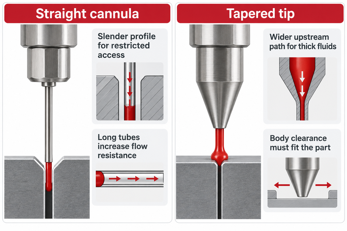
Choose a straight cannula when a narrow outside profile is essential in ensuring clearance or when precise access controls the job. Compare a tapered tip when a thick material needs a less restrictive flow path and there is room around the joint. Selecting the right needle means that the complete geometry must be matched rather than assuming that equal gauge labels signify equal performance.
Straight cannula
- Slender profile for restricted access.
- Length options for reaching recessed joints.
- Small bores and long tubes increase flow resistance.
Tapered tip
- Wider upstream path for thick fluids.
- Body clearance must fit the part.
- Outlet size and material remain family-specific.
When does a high precision tapered blunt needle tip help?
A tapered blunt tip helps when a thick material meets too much resistance in a straight cannula and the wider tip body fits the work area. The recommendation by Nordson is to select this tip geometry for such applications. Look at the outlet dimensions and the shape of the deposited adhesive, as well as the flow. The choice of needle gauge still has to fit the part.
Nordson states that with thicker pastes, increased pressure may worsen control or cause the material to separate. A technical feature on thick-material dispensing describes drooling and backpressure associated with undersized orifices.
Jet-valve needles, on the other hand, use their motion and internal nozzle geometry to form and release droplets. Do not substitute a syringe-tip gauge from this table for the valve manufacturer’s specified assembly. Even with contact dispensing the outlet must cleanly deliver the adhesive to the workpiece.
Choose Needle Length for Access and Flow
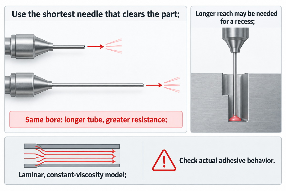
Pick the shortest needle that gives clearance to the dispensing location. With the same bore, increased straight tube length increases resistance in a laminar flow model. A longer needle may be better to reach a more recessed joint.
“In addition, long, straight needle tips are more restrictive than short or tapered needle tips.”
The Poiseuille tube-flow model explains the direction of this length effect under steady laminar, constant-viscosity conditions. Filled and shear-dependent adhesives require their actual operating behavior to be checked. NIST studies on viscoelastic fluids show that elasticity can cause flow instabilities at low Reynolds numbers. Use the tube model to compare constraints, rather than calculate a universal pressure setting.
When changing from a long tip to a short one, consider the fixture, approach angle and stand-off. The outside size of the needle may limit access before the bore limits the flow. Reach is an important factor to consider when selecting a replacement. Be sure to record the cannula length on the order to ensure the replacement is of the same length.
Match Tip Materials to Adhesive Chemistry
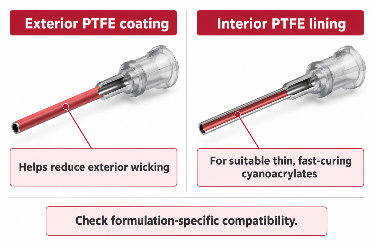
Match the wetted parts of the tip to the adhesive: cannula, lining, hub and any other bonding agent in the assembly. Stainless steel, flexible polymer and PTFE-lined tips solve different application needs. The material name helps shortlist the family, while the adhesive formulation and supplier’s compatibility guidance determine whether it belongs in the study.
Nordson differentiates an exterior PTFE coating used to minimize the risk of wicking of fluids from a PTFE lining for thin, fast-curing cyanoacrylates. Specify which construction of flexible or PTFE-lined tip is needed when comparing dispensing tips.
Light-curable formulations also need suitable light protection along the fluid path. Dymax identifies incompatible materials and transparent fluid lines as common causes of trouble with its light-curing adhesives. Check light protection along the whole tip and fluid line, not just a black hub.
Keep sample comparisons of a material substitution separate from those of a bore change. Otherwise, a changed result leaves two potential causes. It makes the next selection harder. Material compatibility and exposure to light play a role in determining the appropriate tip construction and whether the needles are suitable, especially in sensitive light-curing applications.
Check Required Flow Within the Dispense Window
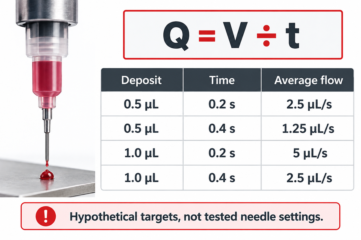
A hypothetical 0.5 µL deposit delivered during 0.2 s of fluid-on time requires an average flow of 2.5 µL/s. This tells us the flow rate we need to achieve. Selection of needle gauge will then have to meet this target based on the actual adhesive, dispenser and the conditions of the deposit transfer.
How do you calculate the required dispensing flow rate?
To calculate the required flow, we use the formula Q = V ÷ t, where V is deposit volume and t is fluid-on time in compatible units. This tells us the average flow rate we need to achieve. This doesn’t take into account needle gauge, operating pressure or the finished size of the dot. Less time may be available for deposit transfer than the overall cycle of the machine would suggest.
| Assumed deposit | Fluid-on time | Required average flow |
|---|---|---|
| 0.5 µL | 0.2 s | 2.5 µL/s |
| 0.5 µL | 0.4 s | 1.25 µL/s |
| 1.0 µL | 0.2 s | 5 µL/s |
| 1.0 µL | 0.4 s | 2.5 µL/s |
OpenStax defines volumetric flow as volume per unit time. With the first example, 0.5 ÷ 0.2 = 2.5. This indicates that, with available time doubled, average flow requirement would be halved while keeping the deposit volume the same.
From the perspective of a production engineer, transfer time may be a more significant constraint than the bore opening. A tip that achieves the target volume, but leaves a tail during withdrawal is no good. During transfer, the needle affects the flow rate. Movement of the tip consumes another part of the cycle. Checking the pressure and actually achieved geometry of the deposit provides more information; a larger needle can’t recover time already consumed.
Compare Sample Kits, Prices and Manufacturer Charts
Compare sample tips with known bores and constructions, then normalize quotations to price per tip for technically comparable products. Different pack quantities can be compared on the same unit basis. Include the amount needed for trials and expected production use, to keep from having an excess of a large pack, which could go unused.
Jensen offers boxes of 50 and bags of 1,000 of its standard dispensing tips; Fisnar offers packs of 50 for the tapered families mentioned here. The NIST Unit Pricing Guide supports consistent per-unit comparison. For a quote, divide the tip cost by the included count for that tip, keeping freight and other charges on a consistent basis.
Suppose two quotations both say 22 gauge, but one names Jensen NT and the other Jensen IT. Address their dimensional difference first, then compare price. When procuring a part, you need to match all specifications of the selected item. Quality requires an acceptable deposit width or dot footprint. Production requires the shot completed on time. A low unit price won’t resolve a mismatch in any of those requirements.
In Assembly’s 2025 dispensing feature, ViscoTec manager Sebastian Gerauer suggests doing dosing tests under actual conditions before series production. For your sample comparison, you should define an acceptable deposit width or dot footprint, position and delivered amount before choosing the production tip.
Determining the appropriate needle gauge ends with that comparison on the part. Using a needle that passes a free-flow check but misses the required deposit leaves the selection unfinished. Considering these factors before a bulk order keeps procurement tied to the demonstrated result.
Turn the Selected Tip into an Orderable Specification
Purchase the exact tip that satisfied both the deposit and timing requirements, preserving its manufacturer, family, part number, bore, length, material, and connection. Keep adhesive and dispenser conditions along with it. This gives procurement a reproducible request and gives production a clear basis to accept a proposed replacement.
- Identify the candidate. Record its series, part number and published dimensions.
- Compare on the actual part. Use the intended adhesive, equipment and deposit criteria.
- Retain the successful conditions. Keep the fluid-on time, pressure or actuation settings and tip position with the selected item.
- Request the production quantity. Preserve the selected construction when comparing quotations or substitutions.
Once a candidate has been selected, the blunt-tip dispensing setup guide covers how to perform checks and address problems. Keep that work separate from choosing a new tip by appearance.
Frequently Asked Questions
Does a higher gauge mean a smaller dispensing needle?
Read answer
Within a given manufacturer’s numbered tip series, a higher gauge generally indicates a smaller opening. Use the actual inner diameter in that series when comparing sizes. A gauge label alone does not identify wall thickness, tube length or tip geometry, and it does not specify the finished adhesive dot size.
Can two dispensing tips with the same gauge have different inner diameters?
Read answer
Yes. Different tip families can assign the same gauge label to different outlet dimensions, and wall thickness changes the bore: in ISO 9626, the standard for stainless steel needle tubing used in medical devices, 25 gauge tubing has a 0.500 to 0.530 mm outside diameter, with a minimum inner diameter of 0.232 mm for regular wall and 0.292 mm for thin wall. Compare the stated inner and outer diameters, material and length on each manufacturer’s chart. Replacing a tip by gauge alone can change dispensing performance or compatibility with the existing dispenser assembly.
Which tip should I try when a thick adhesive flows too slowly?
Read answer
Consider a larger bore or a tapered tip if the required deposit and access allow it. A shorter needle may also reduce flow resistance. Keep the adhesive’s fillers, curing behavior and material compatibility in view. A candidate that flows faster still needs to produce the required deposit within the available dispensing time.
Are hub colors interchangeable between manufacturers?
Read answer
Treat hub color as a catalogue aid, not a dimension. Read the gauge, bore and part number together in the supplier’s chart. If you change suppliers or tip families, compare those dimensions before assuming that matching colors identify equivalent tips.
Can stainless steel dispensing needles be reused?
Read answer
Stainless steel construction doesn’t by itself make a dispensing needle reusable. Follow the specific manufacturer’s intended use and cleaning guidance. Adhesive residue, a partially cured plug or damage to the bore can change delivery even when the outside looks clean. For a production process, a reused tip must also meet the process requirements. If the supplier specifies single use, don’t treat a visual inspection or a solvent rinse as evidence that its performance has been restored.
Can needle gauge predict the final glue dot diameter?
Read answer
No. The outlet is one influence on the deposit. Dispensed volume, adhesive behavior, substrate and tip position also affect dot size. Treat supplier ratios as starting conditions for trials rather than a reliable conversion from gauge to finished dot diameter.
Are Luer-lock dispensing needles compatible with every dispenser?
Read answer
No. A Luer-lock label describes a connection family, not universal compatibility with every valve, cartridge or syringe assembly. Check the dispenser’s intended fitting, the needle hub and any required adapter. Pressure limits and chemical compatibility also depend on the complete assembly. When ordering a replacement, retain the connection information alongside bore, length and material. If the interface is unclear, identify the dispenser model and fitting before selecting the tip, rather than relying on a photograph or hub color.
Build a focused needle sample set
Send Ebestron the adhesive name, required deposit, access dimensions and dispenser connection. Our dispensing needle sample-kit builder organizes candidate families and gauges for your request.
The comparison uses named manufacturers’ published dimensions. The flow examples use hypothetical inputs, which aren’t customer trial results or validated dispenser settings.
References & Sources
- NIST: Fluid Suspensions and Emulsions
- NIST: Rheology
- OpenStax: Viscosity and Laminar Flow; Poiseuille’s Law
- OpenStax: Flow Rate and Its Relation to Velocity
- Darryl J. Small, ASI: Dispensing Small Drops of Low-Viscosity Adhesives Using Diaphragm Valves
- Jim Camillo, Assembly: Dispensing Thick Materials
- NIST SP 1181-2025: Unit Pricing Guide
- Austin Weber, Assembly: How to Error-Proof the Dispensing Process