
Get in touch with Ebestron Company


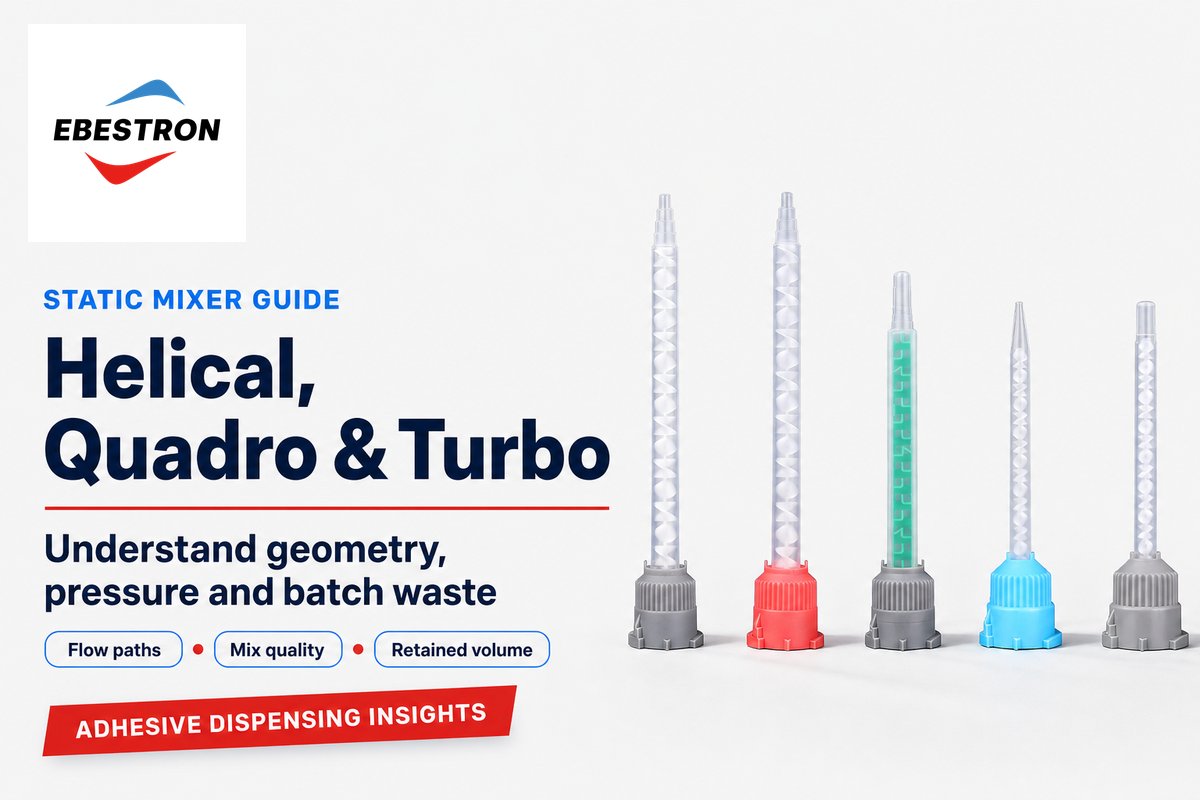
Helical, Quadro & Turbo Static Mixers use fixed internal elements to break apart and recombine the flow of the two adhesive components. Their primary differences are in the kinds of paths those elements create, the space required for effective mixing, and the amount of material left over after dispensing. A shorter nozzle can help save adhesive, but a mixer’s name alone doesn’t determine the quality of the mix or impact the total cost.
This guide provides information useful for comparison of three static mixing designs, situations where lower retained volume is an advantage, and provides a specific example illustrating the concept. The starting point is a description of the adhesive process including: the required component ratio, behavior of the material, and the quality of the finished part.
Geometry tells you
- How streams divide and change position
- How elements occupy the available length
- Which internal paths deserve comparison
The application determines
- Whether the mixed adhesive meets its quality requirement
- How much pressure the complete assembly needs
- How much material is discarded over the batch
How static mixers blend two adhesive components
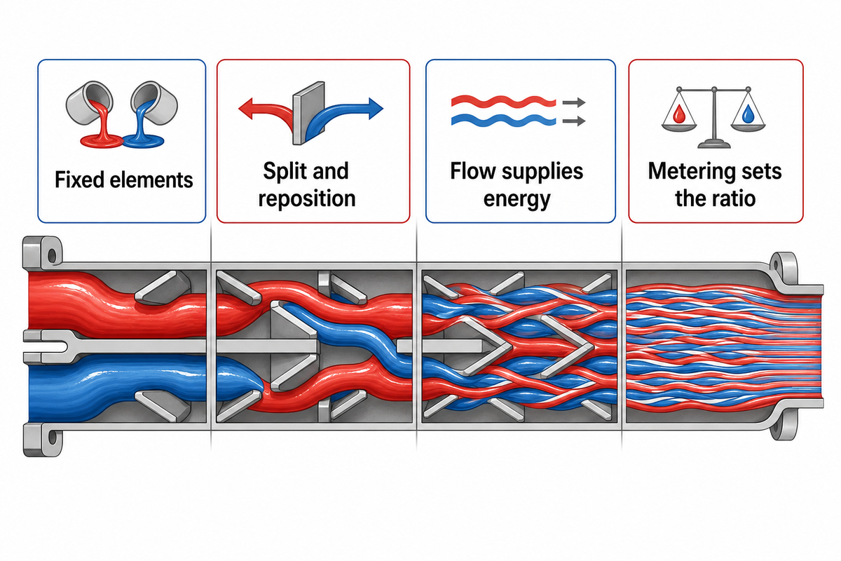
A static mixer consists of fixed elements that change the flow path of the components. The presence of the mixing elements repeats this process numerous times. However, the dispensing system in the control arrangement determines how much of each component flows through the elements. As a result, fluid mixing remains separate from ratio control.
How Does A Static Mixer Work?
A static mixer uses fixed elements to split and reposition the flowing material. The elements allow progressively smaller regions of each component of the material to be mixed. The mixing element remains still. The internal elements use the energy of fluid flow to control how that flow is redistributed.
Picture two streams entering side by side. When put in the same tube, there’s a large interface between them. Repeated division and reorientation spread each stream across the mixer outlet. In a liquid static mixer, contact between components is distributed to finer regions. In laminar flow, rearranging components in this way is very useful when vigorous turbulent mixing is absent. The University of Michigan describes this in its static mixer example.
“Additional pumping energy needed because of pressure losses.”
Metering and mixing are kept as separate functions. For a 2:1 volume ratio formulation, the dispensing system is required to deliver that ratio before the nozzle can distribute the components. In the absence of hardener, adding elements can’t replace the missing hardener. The distinction is made to avoid confusing a mixing problem with a cartridge or starting problem.
Helical static mixers: alternating turns and repeated division

Helical static mixers use elements with a helical shape to guide material through successive twisted elements, typically with alternating handedness. Each change in orientation divides and redirects the material in the flow stream again. This repeated action creates finer distributions along the mixing length, making the helical design easy to understand as a sequence of connected mixing stages.
Nordson EFD describes its spiral elements as being twisted by 180 degrees, with adjacent elements having leading and trailing edges that are perpendicular to each other. The design of static spiral elements uses each helical blade to guide and redirect fluid, while the junction between elements changes which portions meet and separate.
The Bakker abstract on a Kenics static mixer describes splitting and shearing at the junctions and stretching and folding in the elements. Mixing with Kenics static mixers is a useful mechanism reference, but a commercial static mixer for disposable adhesive dispensing can differ in size and construction.
Having a better understanding of elements related to flow and mixing with Kenics supports an understanding about the significance of repeated reorientation. In laminar mixing with Kenics in-line mixers, it’s the arrangement of the various streams that places portions in new relationships, rather than a rapidly rotating mechanism. This principle is illustrated in the Kenics mixer, and to determine its utility, the dimensions and operating conditions of the adhesive nozzle should be reviewed.
Element count in a nozzle specification describes a type of static mixer and its mixing characteristics. Additional helical elements provide greater mixing stages, but may also alter length, pressure loss, and retained adhesive. The spiral shape is a common feature; the complete part number and adhesive will determine if the additional stages are of value.
Quadro static mixers: compact square flow paths
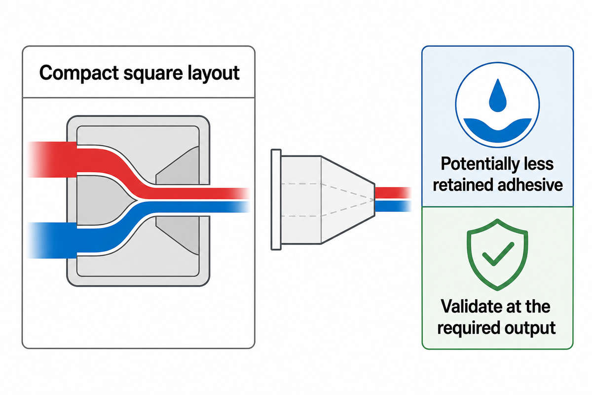
Quadro static mixers use a compact element arrangement to split and reposition material in a series of steps. Their main appeal is the possibility of reaching the required distribution in a shorter assembly. That can reduce the adhesive held in the mixer when it is discarded and improve access where nozzle length is restricted.
In medmix’s description of mixing technology, Quadro elements squeeze and rearrange the streams, while helical elements redirect them through alternating twists. These describe ways of producing effective mixing within a constrained axial distance. A square outer housing, however, doesn’t fully characterize the element within it.
Schöck’s discussion of mixing efficiency also describes a practical limitation: favorable comparisons of Helix and Quadro elements for simple-to-mix materials can change with demanding component ratios and viscosity contrast. Compactness merits its worth when the preferred configuration yields satisfactory adhesive at the stipulated output rate. It isn’t a basis for comparison of unrelated lengths as if their performance were identical.
Turbo static mixers: a design name, not a turbulence guarantee
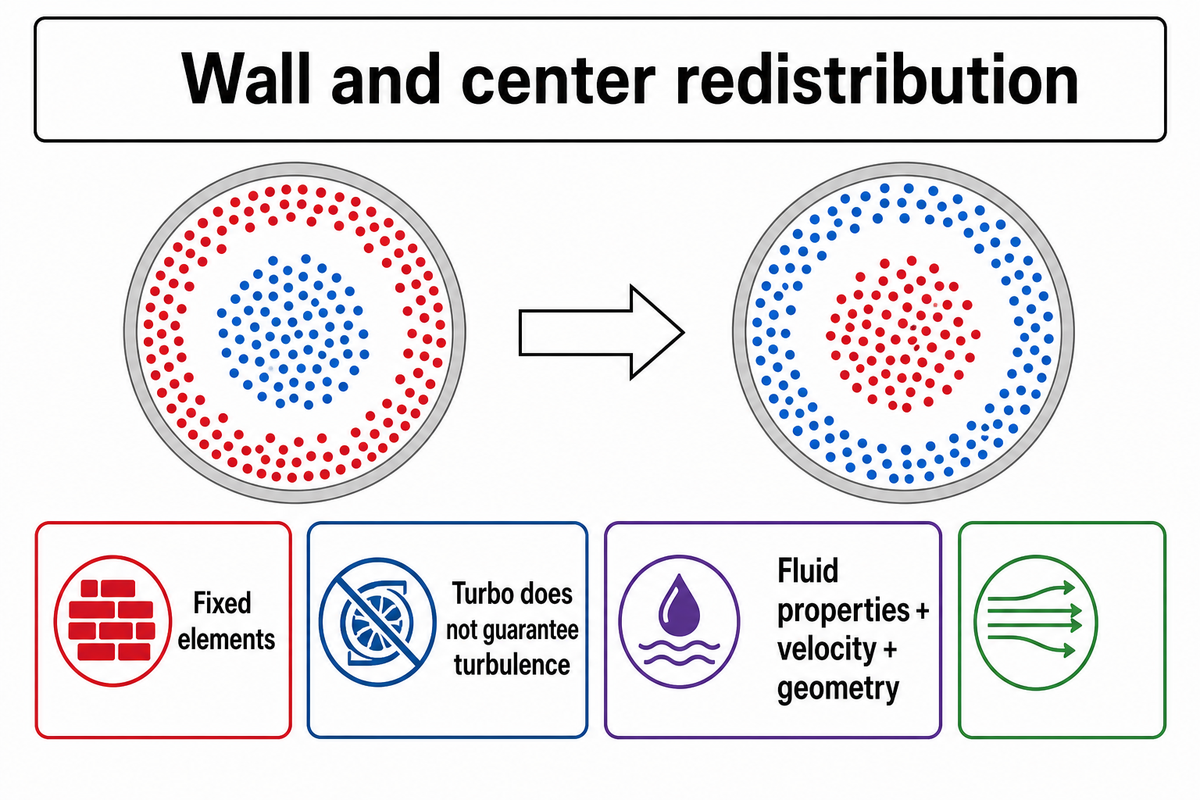
Turbo static mixers are of a fixed element design. In the Turbo design by Nordson EFD, alternating elements are coupled with intermittent flow inverters to redirect the material between the wall and the center. This redistribution addresses the position of material within the nozzle; the term Turbo doesn’t delineate a turbulent flow regime.
Flow characteristics depend on fluid properties, velocity and geometry. Viscous two-part adhesives can mix through laminar rearrangement without a turbulent vortex. A powered rotor is a separate mechanism, covered in our guide to static and dynamic mixing for two-part adhesives .
Careful reading is required for product-family names as well. For example, on Nordson’s Turbo page, several series are listed along with OptiMixer info. A percentage comparator for a given model shouldn’t become a guarantee for the series as a whole. The three mixers’ actual layouts, dimensions and inlet assemblies should be compared rather than assuming that “Turbo” is an indicator of speed or quality of mixing.
Pressure drop and mixing quality: compare complete configurations
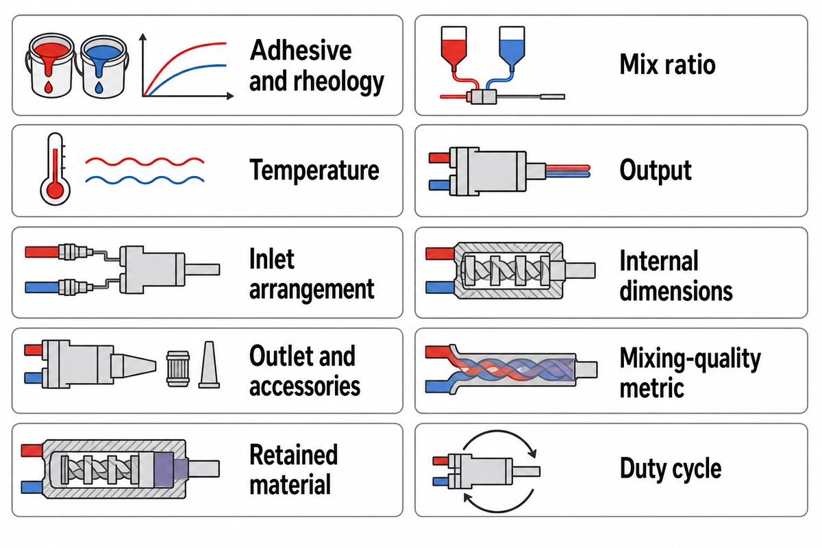
Static mixers, including novel static mixing designs, should be compared at the same material condition, delivered ratio and useful output, and using a defined mixing-quality measure. Improved mixing means a better result against that measure, rather than a stronger-sounding product name. Pressure drop across the complete assembly then states the demand associated with that result. Mixing uniformity and pressure should be evaluated together.
A low pressure drop is appropriate when the system must deliver a specified bead or shot. However, a low pressure reading doesn’t say much about distribution. A uniform color of the adhesive doesn’t prove the absence of fine streaking. Curing-property measurements should be taken to determine the properties of the cured joint. The comparison should relate to flow and mixing.
| Parameter | Compare on this basis | Why it changes the result |
|---|---|---|
| Adhesive and rheology | Same formulation; both component viscosities and measurement conditions | One blended viscosity hides the contrast between streams |
| Mix ratio | Same specified ratio; distinguish mass from volume | Unequal streams place different demands on redistribution |
| Temperature | Same material temperature in °C | Viscosity and reaction behavior can change with temperature |
| Output | Same flow rate in mL/min or shot volume and timing | A slower test can give an easier pressure reading |
| Inlet arrangement | Same component entry positions and adapter configuration | Initial distribution reaches the first element before mixing begins |
| Internal dimensions | Element geometry, internal diameter and mixing length in mm | Outer appearance and nominal element count omit the flow path |
| Outlet and accessories | Same tip, extension and pressure measurement locations | Restriction outside the elements contributes to measured pressure loss |
| Mixing-quality metric | Same sampling plane, method and acceptance criterion | CoV, streak dimensions and cured-part tests answer different questions |
| Retained material | Volume in mL for the complete discarded assembly | Connector or tip retention can change the material total |
| Duty cycle | Same number of starts, stops and replacements | Startup purge and discarded mixers accumulate across the batch |
An example would be a team comparing a short square nozzle with a longer spiral. They could use the same cartridge but different outlet tips. The resulting pressure readings would describe two complete assemblies, not just the internal elements. Keeping the outlet and measurement points the same separates a geometry question from a dispensing-tip question.
What role does Computational Fluid Dynamics play in analyzing helical mixing elements?
Computational fluid dynamics simulations (CFD simulations) of the flow field and component placement within a defined mixer model predict where material streams within the mixer and provide insight into how design changes might impact pressure and mix. Comparisons should address rheology, inlet conditions, geometry and the mixing metric, then validate the results obtained against measurements.
Using computational fluid dynamics gives insight into the internal behavior of a system that isn’t captured in an outlet sample. Numerical simulation represents the conditions: a pipeline model with a different pipe diameter or a different fluid isn’t a representation of the adhesive assembly. Alberini and colleagues’ Kenics KM research gives insight into the importance of mixer design, along with inlet configuration and the method used to evaluate mixing.
Those investigations were carried out on shear-thinning fluid systems with different rheology and inlet conditions. The results were compared using different concentration and striation-based measures. That makes a difference when judging the results obtained against measurements, especially in the case of a new static mixing design.
Viscosity, ratio and element count: why simple rankings fail
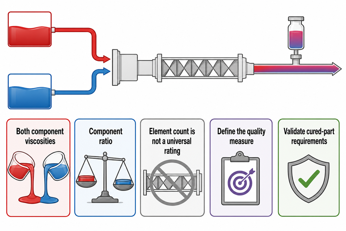
Both component viscosities and their ratio affect how streams transform within a static mixing device. For example, a thin hardener entering a thicker resin doesn’t always spread like two fluids with similar behavior. Element count alone can’t describe the interaction. An element count that works well for one formulation shouldn’t be taken directly to another.
Regner and colleagues studied this behavior in a numerical study of viscosity ratio. A 40 mm Lightnin Series 45 model showed that the mixer worsened as the viscosity difference increased, while a different behavior was observed near the conditions where secondary motions became important. The results show the behavior of material and the flow field, rather than a transferable viscosity limit for adhesive nozzles.
The coefficient of variation, or CoV, represents concentration variation relative to the mean. It describes concentration distribution at a selected sampling point in a process. A lower CoV using the same measurement technique indicates a more even concentration at that point; this doesn’t necessarily satisfy the adhesive bond strength requirement. Sample spacing, as well as the size of remaining streaks, can play an important role in the downstream process.
“It is far more reliable to compare mixer options using direct empirical data.”
Let’s say a dispensing line changes from a balanced formulation to one with a small, low-viscosity component. Keeping the old element count preserves a catalog number, not the previous mixing conditions. The practical comparison is whether each candidate reaches the same application quality at the required delivery rate. Different numbers of mixing stages may be required in different static mixer designs.
Retained volume and waste cost: a worked comparison
Using less retained volume reduces adhesive waste with each filled and discarded mixer, as Joachim Schöck of medmix explains in his discussion of waste volume. Batch savings include the purchase price of each nozzle and material purged during starts and restarts. Compare candidates that meet the same finished part requirement first, then calculate waste and nozzle cost for the same accepted output.
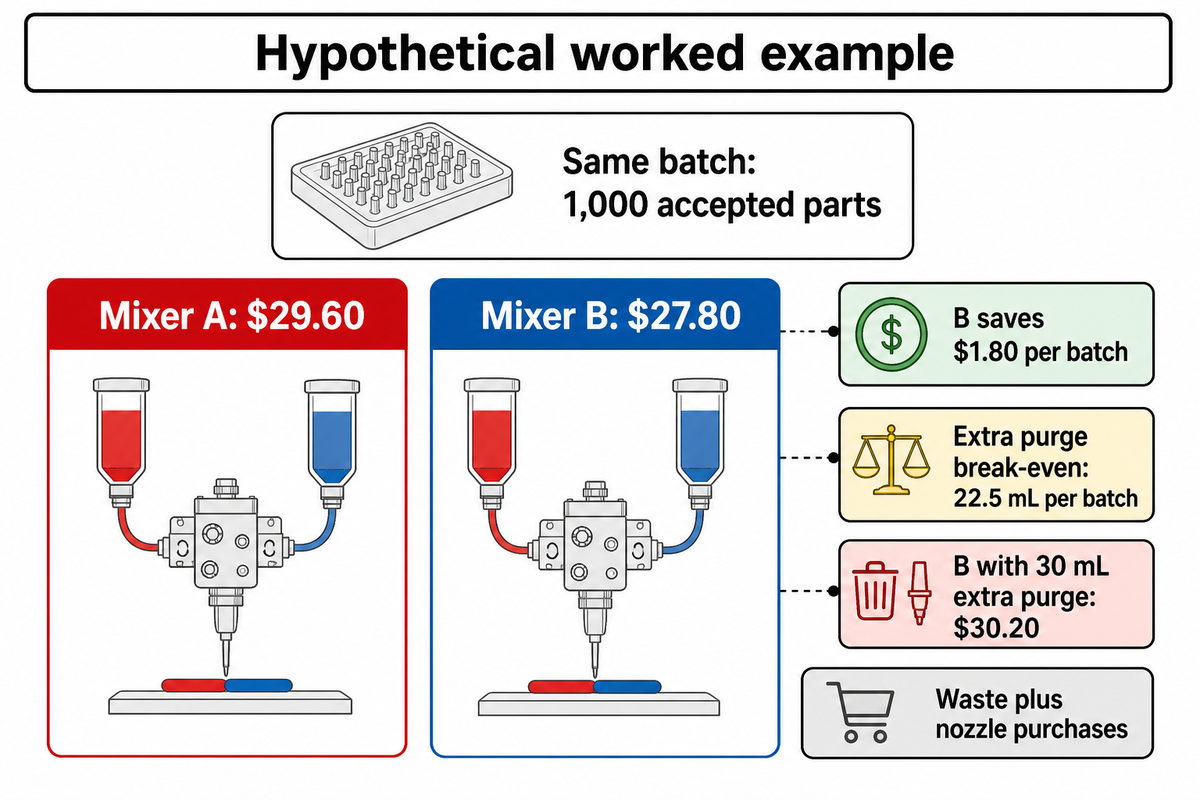
Example: Assume two approved candidate configurations each produce 1,000 accepted parts using 20 nozzles. Assume adhesive costs $0.08/mL and total purge is 100 mL for each option. Mixer A retains 6 mL and costs $0.60 each; Mixer B retains 3 mL and costs $0.75 each. These inputs provide an estimate of discarded adhesive and nozzle purchases for each alternative, excluding labor, disposal, and rejected parts.
| Cost input or result | Mixer A | Mixer B |
|---|---|---|
| Material retained in 20 discarded nozzles | 20 × 6 = 120 mL | 20 × 3 = 60 mL |
| Total purge | 100 mL | 100 mL |
| Discarded adhesive cost | 220 × $0.08 = $17.60 | 160 × $0.08 = $12.80 |
| Nozzle purchase cost | 20 × $0.60 = $12.00 | 20 × $0.75 = $15.00 |
| Waste plus nozzle cost | $29.60 | $27.80 |
The calculation is: batch cost = (nozzle count × retained volume + total purge volume) × adhesive cost per mL + nozzle count × nozzle price. Mixer B saves $4.80 in retained adhesive but adds $3.00 in nozzle purchases, leaving a $1.80 batch saving.
The crossover point is when savings from reduced retention equal the cost of additional purge. In this case, net savings from reduced retention are $1.80 and cost of additional purge is $0.08/mL. The crossover point is 1.80/0.08 = 22.5 mL of extra purge across the whole batch. If Mixer B needed 30 mL of extra purge, its total cost would be $30.20, or $0.60 more than mixer A. While retaining less material saves adhesive inside the mixer, the additional purge outweighs the cost advantage.
This is why a unit price comparison and a volume comparison of retained adhesive can yield different results. The useful purchasing figure is the cost of the accepted output for which the purge boundary and replacement count are defined.
Stop-start dispensing changes the waste comparison
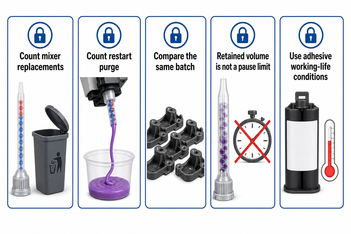
Stop-start dispensing adds two variables to the retained volume comparison. The first is the frequency mixers are replaced. The second is the volume of material discarded at each restart. A nozzle continuously used during a batch can contribute to cost differently than a nozzle used in a series of short jobs separated by long intervals.
A discussion on Eng-Tips on intermittent epoxy work describes the mixed material burden on equipment. That’s true even when the internal volume of the nozzle is small. Our guide on two-part adhesive cartridges covers the steps of the process; this article covers the totals and replacements it creates.
Retained volume is different from residence-time distribution. Fluids don’t all flow through an inline mixer at the same velocity. Poumaëre and colleagues’ residence-time study looks at that distribution for different inline mixing geometries. Dividing the volume by flow rate provides a nominal mean, not the age of every part of the material, or a universal allowable pause.
ISO 10364:2024 specifies methods for determining the pot life of multi-part adhesives. Different methods need not yield the same results. For batch planning, it is advised to use the working life conditions of the adhesive and the actual stop pattern rather than converting a nozzle volume to a cure time.
From geometry knowledge to a defined application
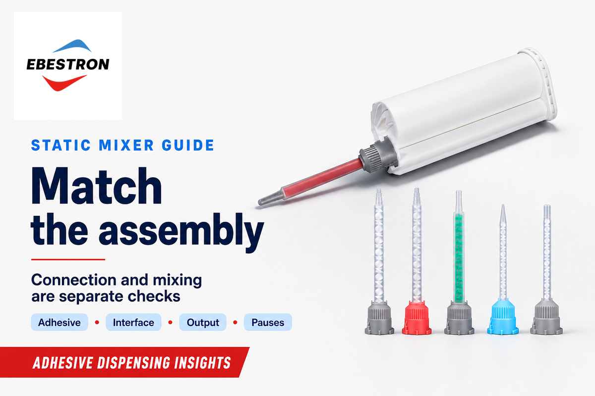
When selecting static mixers, the combination of the adhesive, the dispensing system and the nozzle assembly is to be considered a candidate specification. The interface determines the connection of the parts; the internal elements determine the mixing path. Keeping the two decisions separate aids the description of an application. It allows treating some square and spiral nozzles differently. Consideration of various static mixing layouts is allowed, but a new static mixer must still satisfy the same requirement.
Ebestron offers 50 mL dual cartridges in ratios of 1:1, 2:1, 4:1 and 10:1. Their mixing nozzles by interface type describe available connection options and internal geometry. Terms used in the static mixing nozzle connection guide explain the connection terminology in more detail.
For an application review, verify the type of adhesive and ratio basis, both component viscosities at operating temperature, target output, cartridge or meter-mix connection, available pressure, outlet requirements and expected pauses. The controlled static-mixing-tube screen provides the separate trial-record method for moving a candidate towards production.
Key takeaway
Choose a complete mixer configuration that meets the adhesive’s quality requirement at the intended output, then compare pressure demand and batch waste. Geometry explains the mechanism; accepted output makes the cost comparison meaningful.
For available configurations and supply details, see Ebestron’s Helical, Quadro & Turbo Static Mixers solution page.
Frequently asked questions
Can two nozzles with the same element count mix differently?
Yes. Element shape, internal diameter, inlet arrangement and formulation can change the result even when the count matches. Two nozzles with the same number of stages can redistribute material differently, so their performance comparison needs the same adhesive, output and quality measure.
What the count leaves out
A mixing stage is a feature of a particular design, not a universal unit of mixing performance. A change in geometry can alter division, shear and redistribution within each stage. Compare the complete configurations at the same output and quality criterion. The count then helps identify the tested nozzle instead of acting as a stand-alone performance rating.
Are Quadro and Turbo interchangeable names?
No. Quadro and Turbo describe commercial design families and shouldn’t be treated as interchangeable part specifications. A square external shape can hide different internal layouts. The exact element assembly, inlet connection and outlet arrangement matter when considering one nozzle as a replacement for another.
How to distinguish the families
Square housings can contain different element sequences, and manufacturers use their own connections and product dimensions. Nordson’s Turbo description includes intermittent flow inverters, while medmix explains Quadro through its own square mixing layout. A replacement needs the appropriate connection and demonstrated application performance. Matching an outer shape or a family name doesn’t establish a matching assembly.
Does a shorter mixer always waste less adhesive?
No. Shorter length can reduce internal retention, but total waste also includes purge and the number of discarded mixers. A small volume discarded repeatedly can outweigh a larger volume discarded once. Internal diameter and the rest of the assembly also affect how much adhesive remains.
Why the batch total matters
Internal diameter, element occupancy and connector volume affect how much adhesive remains in a filled assembly. The duty cycle determines how many such assemblies are discarded. In the worked example, a retention advantage remains real even after extra purge reverses the cost saving. Counting the full batch separates the nozzle’s physical volume from its contribution to production waste.
Can more mixing elements correct an incorrect component ratio?
No. Extra elements redistribute the material delivered to them; they can’t supply a missing component. In a static liquid mixer, an incorrect incoming ratio remains an incorrect overall ratio even after the streams become evenly distributed. Delivery accuracy must therefore be addressed before assessing nozzle mixing quality.
Metering and mixing are separate
A ratio problem must be addressed in the delivery system or operating sequence. A uniformly colored bead can still have the wrong overall composition. Correct delivery comes before assessing whether the chosen nozzle distributes the components adequately.
Can air bubbles appear even when the components were degassed?
Yes. Degassing the stored components doesn’t remove air already present in an empty flow path. Filling a nozzle at startup is a separate event from removing bubbles in a storage container. The timing and appearance of bubbles help distinguish those stages of the dispensing process.
A useful startup distinction
An Eng-Tips epoxy discussion raises this exact concern. Startup filling, component delivery and the material itself are different possible contributors. Bubble appearance alone doesn’t identify which geometry performs best, and the thread should be read as a troubleshooting observation rather than a controlled comparison.
References & Sources
- Mixers University of Michigan, Visual Encyclopedia of Chemical Engineering Equipment.
- Laminar Flow in Static Mixers with Helical Elements Andre Bakker, author abstract hosted by Academia.
- Parameters to Quantify Mixing Efficiency of Static Mixers Joachim Schöck, Adhesives & Sealants Industry, 2023.
- Assessment of Different Methods of Analysis to Characterise the Mixing of Shear-Thinning Fluids in a Kenics KM Static Mixer Using PLIF Alberini and colleagues, Chemical Engineering Science, 2014.
- Influence of Viscosity Ratio on the Mixing Process in a Static Mixer: Numerical Study Regner, Östergren and Trägårdh, Industrial & Engineering Chemistry Research, 2008.
- The Next Generation of Static Mixing Nozzles Eric Ronning, Adhesives & Sealants Industry, 2022.
- Residence Time Distributions for In-Line Chaotic Mixers Poumaëre, Pier and Raynal, Physical Review E, 2022.
- ISO 10364:2024: Adhesives, Determination of Pot Life (Working Life) of Multi-Part Adhesives International Organization for Standardization.
Discuss your adhesive dispensing application with Ebestron
Share the formulation, cartridge connection, output requirement and stop pattern so the nozzle discussion starts with your process.
Written by CYH.